
Scooter
This space for rent...
I needed to get around to servicing the steering head bearings on my STeed since that was the only item in the maintenence chart that I've neglected over the years. Mind you, I've never had any issues at all with my steering but I decided that I'd replace the existing ball roller bearings with the much talked about tapered roller bearing. After performing proper due diligence I decided to purchase the All Balls kit instead of the CBR Bearings kit mainly due to cost concerns. The cost of the All Balls kit was $26.86 and although I did not contact CBR for the price of their kit, I've seen others post that it was in the upper $50 range. I figured that in this application, it wasn't necessary to spend the extra coin on a bearing made in Japan versus one made in China and after I received the kit and inspected the bearings, I have no regrets choosing the ABs kit.
My original intention was to contact John O. and see if I could get my hands on the HONDA ST1100/ST1300 STEERING STEM RACES/BEARINGS R&R TOOL KIT but I came to find out that the kit was already in use. The only tool in that kit that I really wanted to get my hands on was the steering stem socket (Honda P/N 07916-3710101 or 07916-3710100) which like most of Honda's tools, has gotten quite expensive over the years. I was resigned to the fact that I was going to have to wait for the toolkit to become available but while searching the net for the Honda version, I stumbled across this thread. You will need to scroll down to post 8 to see what I am referring to here.
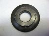
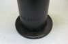
Checking into my stock of tools I noticed that I had a 32mm deep well impact socket that I had picked up last year and after placing it on top of the adjusting nut I saw that it had the right outer diameter to work as a substitute tool. Here is a picture of the adjusting nut removed from the bike:
Placing the socket and aligning it on top of the nut provided an easy way to mark the socket where the grinding need to take place.
I simply used an angle grinder to cut the four notches into the socket. Yeah, it would have been nice to give it to my brother and he could have put it on a CNC machine and ground out some beautiful slots into it but I figured that if I was going to MacGyver this, I wanted it to look the part. I already had some hose clamps but the part I didn't have was some 3/16" square bar keys. So I went to the local Fleet Farm and scored a one foot section of square stock for 99? and cut four one inch pieces off of the bar.
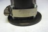
After assembling everything this is what I ended up with:
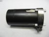
I placed the notches on the socket so that they stayed away from any of the six edges of the cutout for the nut in order to minimize any weakening of the socket in case I ever need to use the socket again.
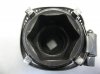
Here is another photo showing the finished tool sitting on top of the nut:
Steering Stem Adjusting Nut Torque Settings
I have to say, one of the most time wasting parts to this whole job was trying to find a definitive answer to how much torque was required to tighten the adjusting nut on the steering stem. Answers ranged anywhere from 1.5 to 2 lbf-ft to well over 30 lbf-ft or to adjusting it by "feel". The bearings used in our machines are also used on almost all of Honda's other bikes so you can find that this topic has been hashed to death out there. I'm also quite familiar to using feel to adjust bicycle stems but I find that there is a lot of trial and error to that method and I didn't want to waste time taking apart the stem assembly multiple times on order to get the setting correct.
I did manage to find one website that posted the following instructions that made some sense to me. Apparently, Honda has produced some bikes using a tapered head bearing and the service manual instructions stated the following:
This procedure is very similar to what is called out for in the ST1300 manual except that the adjusting nut is torqued is 5.8 lbf-ft instead of 22 lbf-ft and the steering stem nut is tightened to 76 lbf-ft instead of 72 lbf-ft. After performing the procedure and assembling the components, I next took a fish scale and measured the steering head bearing pre-load and was very happy to find that I was within the range specified by the manual, measuring about 4 lbf (range is 3.5 to 4.6). Hopefully, this information will be of use to some others.
I have to say that the tool worked wonderfully. It could easily handle the torque required to perform the job. The total cost is very reasonable. I'm sure that one could pick up a 32mm socket from Harbor Freight for a small price and I suppose you could easily weld the angle bar to the socket for a more permanent solution. Another possible solution is to pick up a socket large enough so that all you need to do is grind out the top of the socket leaving yourself the four prongs required.
Now I suppose the proof is in the pudding and trying to get out and actually ride the bike to see how it feels. That will have to wait until the salt gets off the roads...
My original intention was to contact John O. and see if I could get my hands on the HONDA ST1100/ST1300 STEERING STEM RACES/BEARINGS R&R TOOL KIT but I came to find out that the kit was already in use. The only tool in that kit that I really wanted to get my hands on was the steering stem socket (Honda P/N 07916-3710101 or 07916-3710100) which like most of Honda's tools, has gotten quite expensive over the years. I was resigned to the fact that I was going to have to wait for the toolkit to become available but while searching the net for the Honda version, I stumbled across this thread. You will need to scroll down to post 8 to see what I am referring to here.
Checking into my stock of tools I noticed that I had a 32mm deep well impact socket that I had picked up last year and after placing it on top of the adjusting nut I saw that it had the right outer diameter to work as a substitute tool. Here is a picture of the adjusting nut removed from the bike:
Placing the socket and aligning it on top of the nut provided an easy way to mark the socket where the grinding need to take place.
I simply used an angle grinder to cut the four notches into the socket. Yeah, it would have been nice to give it to my brother and he could have put it on a CNC machine and ground out some beautiful slots into it but I figured that if I was going to MacGyver this, I wanted it to look the part. I already had some hose clamps but the part I didn't have was some 3/16" square bar keys. So I went to the local Fleet Farm and scored a one foot section of square stock for 99? and cut four one inch pieces off of the bar.
After assembling everything this is what I ended up with:
I placed the notches on the socket so that they stayed away from any of the six edges of the cutout for the nut in order to minimize any weakening of the socket in case I ever need to use the socket again.
Here is another photo showing the finished tool sitting on top of the nut:
Steering Stem Adjusting Nut Torque Settings
I have to say, one of the most time wasting parts to this whole job was trying to find a definitive answer to how much torque was required to tighten the adjusting nut on the steering stem. Answers ranged anywhere from 1.5 to 2 lbf-ft to well over 30 lbf-ft or to adjusting it by "feel". The bearings used in our machines are also used on almost all of Honda's other bikes so you can find that this topic has been hashed to death out there. I'm also quite familiar to using feel to adjust bicycle stems but I find that there is a lot of trial and error to that method and I didn't want to waste time taking apart the stem assembly multiple times on order to get the setting correct.
I did manage to find one website that posted the following instructions that made some sense to me. Apparently, Honda has produced some bikes using a tapered head bearing and the service manual instructions stated the following:
Honda factory service manual for my XR650R that has tapered bearings on the steering stem from the factory says:
Tighten the steering head adjustment nut with the steering stem socket.
Torque 29 N.m (3.0 kgf-m, 22 lbf-ft)
Turn the steering stem lock-to-lock enough times to seat the bearings.
Loosen the adjusting nut to torque of 0 N.m, and retighten to the specified torque.
Torque: 8 N.m (0.8 kgf-m, 5.8 lbf-ft)
Install the top bridge and washer.
Loosely install the stemp nut.
Insert the fork legs.
Tighten the stem nut to the specified torque.
Torque: 98 N.m (10.0 kgf-m, 72 lbf-ft)
This procedure is very similar to what is called out for in the ST1300 manual except that the adjusting nut is torqued is 5.8 lbf-ft instead of 22 lbf-ft and the steering stem nut is tightened to 76 lbf-ft instead of 72 lbf-ft. After performing the procedure and assembling the components, I next took a fish scale and measured the steering head bearing pre-load and was very happy to find that I was within the range specified by the manual, measuring about 4 lbf (range is 3.5 to 4.6). Hopefully, this information will be of use to some others.
I have to say that the tool worked wonderfully. It could easily handle the torque required to perform the job. The total cost is very reasonable. I'm sure that one could pick up a 32mm socket from Harbor Freight for a small price and I suppose you could easily weld the angle bar to the socket for a more permanent solution. Another possible solution is to pick up a socket large enough so that all you need to do is grind out the top of the socket leaving yourself the four prongs required.
Now I suppose the proof is in the pudding and trying to get out and actually ride the bike to see how it feels. That will have to wait until the salt gets off the roads...
Last edited: