
- Joined
- Dec 12, 2004
- Messages
- 1,282
- Age
- 76
- Location
- Weatherford, TX
- Bike
- '16 Versys 650LT
- STOC #
- 1134
I initially posted this write-up on a Bandit forum that I frequent a couple of months ago. Because the folks on that forum are a bit less enamored of farkling (and thus not as experienced), I went into more detail than I normally would on ST-O. Anyway, there are a few Bandit owners on ST-O so I thought someone might find this report useful.
NOTE: If you'd like to download a pdf of this procedure, click HERE.
*****************************************************************************
A couple of weeks ago I finally got off my duff and installed some electrical farkles on my Bandit. Been wanting to do this for a couple of years but for various reasons, main one of which was just old fashioned procrastination, I never got around to doing it. Finally did the deed. Now I have the ability to use GPS, Radar Detector, plug in air pump, etc. Below are some pics and explanations that will hopefully help out those who wish to do the same.
Here is the list of what I added:
Switched power source for electrical goodies
2 electrical sockets
Exterior mounted trickle charger connection
Voltmeter
EZ Tag
I. POWER SOURCE:
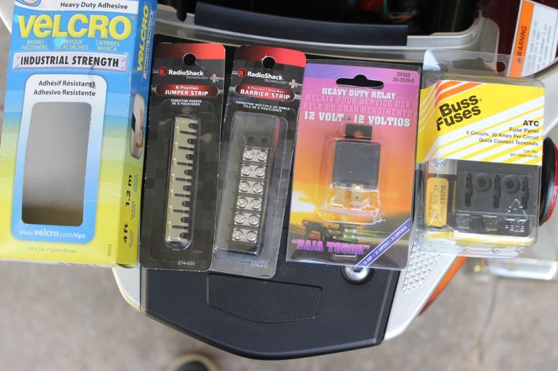
The first order of business was to install the switched power source. So what did I need to accomplish this? The pic below shows the core of what is required. I got these from my local auto parts store, Radio Shack, and Home Depot:
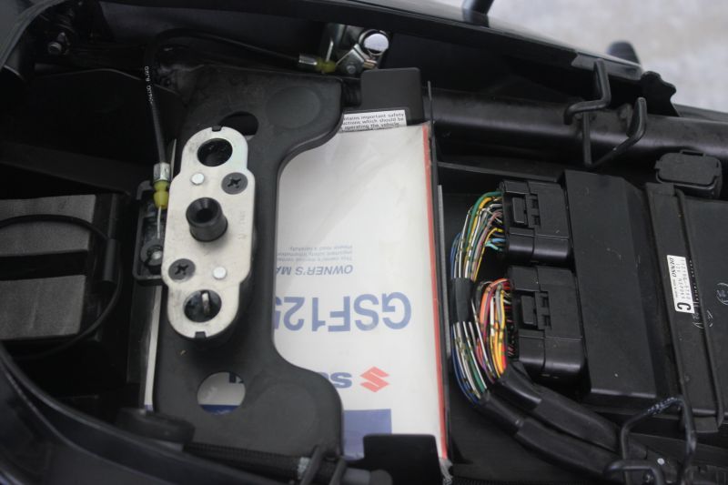
Now to find a location to put all this stuff. There's not a lot of spare room on the Bandit, especially if you want to keep the tool pouch. As it turns out, there's a perfect spot to place a fuse block, relay & ground strip.... under the seat where the owner's manual resides:
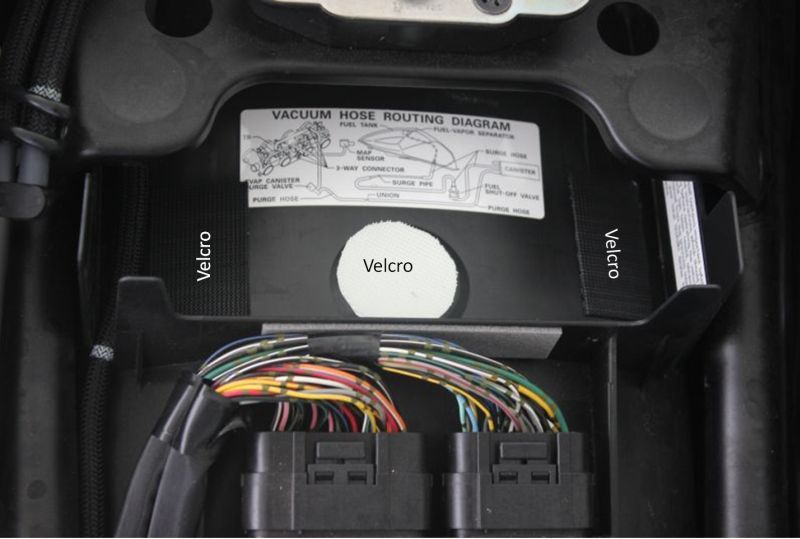
I just yanked the manual out and was left with an area that was almost tailor made for placing electrical stuff. I then cut some velcro and applied it inside of the owner's manual storage area:
And here is a picture of these items placed in the owner's manual tray after installation:
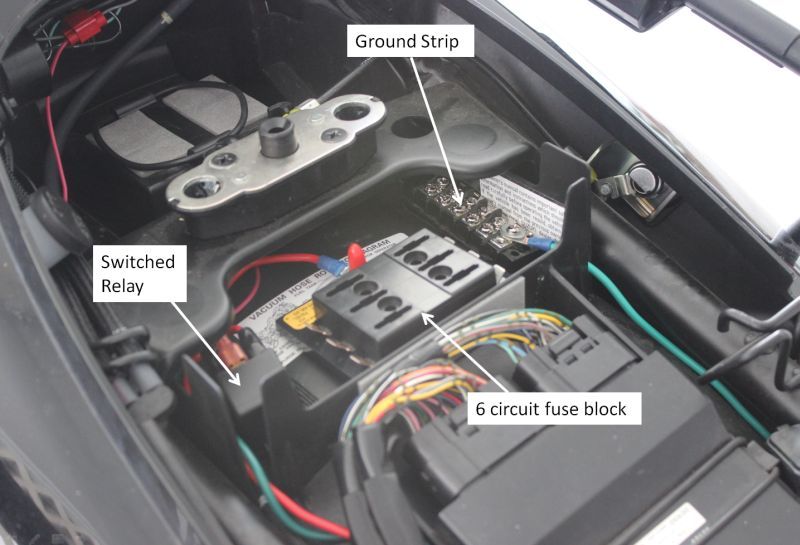
A little explanation before proceeding. In order to have switched electrical power to multiple items, it's best to use a relay. The relay activates when the ignition key is turned on. When activated, it supplies power directly from the battery to whatever you want it to go to. In this case, it's going to a 6 circuit fuse panel. From there it goes to whatever you're trying to electrify.
The wire I used from the battery to the relay and from the relay to the fuse block is 12 gauge. That's heavy enough that you don't have to worry about overloading it.
Note the green wire attached to the ground strip. This comes straight from the negative terminal of battery. Like the positive lead, this also is 12 gauge wire. I used green for all ground wires so I wouldn't get them mixed up. Green is the standard color used for ground on every Honda I have ever owned so I thought I'd use that scheme on the Bandit.
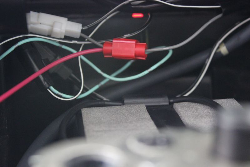
How does the relay activate? If you'll look in the upper left corner in the picture above, you'll see a red wire and a red inline tap. This wire is tapped to the license plate light wire and the other end is connected to the relay. When the ignition switch is turned on, the license plate circuit becomes powered up. With the inline tap in place, it then sends juice to the relay which activates, which in turn provides power to the relay's line out terminal directly from the battery.
Below is a close-up picture showing the tap on the license plate light lead (gray wire). This photo is looking directly into the back end of the bike. The light gray area is the shelf where the OEM toolkit is stored.
If you've never dealt with general purpose relays before, you'll be happy to know that they all seem to have a very convenient numbering scheme on the terminals that allow you to hook them up properly. Below is a really great chart that I found on http://www.rattlebars.com/mtz/hornrelay.html . I've also seen this very same chart on other sites:

You can see the terminals that accept wires that come directly from the battery (#'s 85 & 30). As mentioned, I used 12 gauge wire (available at any auto parts store) for both the positive & negative leads. The trigger (coming from the license plate light wire) uses relatively little juice so I used a much thinner 18 gauge wire (runs to terminal 86). For the line out to the fuse block I again used 12 gauge wire.
For attaching the wires to the slip-on terminals, I like to use crimp on,insulated connectors where possible. The insulation reduces the chance of a short. An example of one type can be seen here:
http://www.radioshack.com/product/index.jsp?productId=2104016 . They can be purchased at any number of places such as auto parts stores, radio shack, etc.
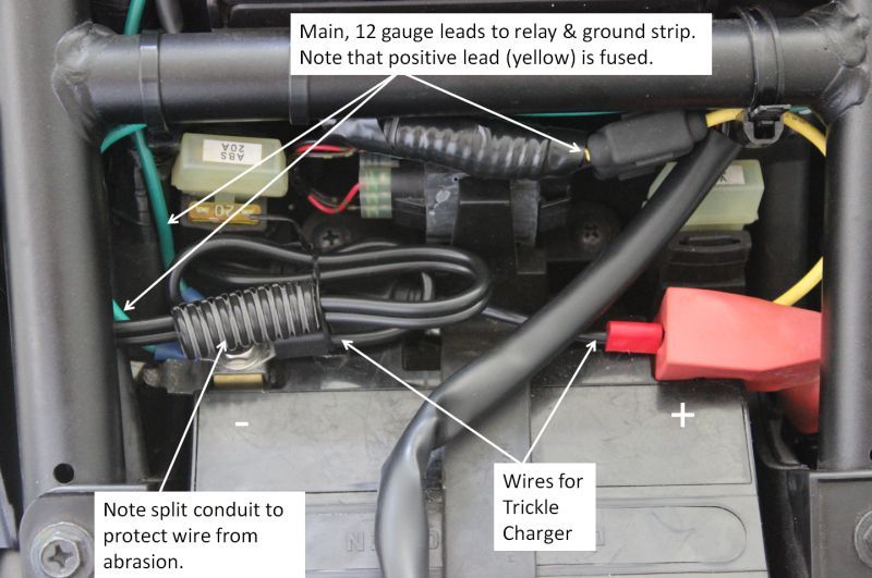
Below is a pic showing the wires connected at the battery. Note the yellow colored lead coming off the battery. This is a 12 gauge, fused lead that I bought at my local auto parts store. It is soldered to the red, 12 gauge lead that runs to the relay. The splice is underneath the black split conduit that you see next to the fuse holder on the yellow wire.
II. VOLTMETER:
My voltmeter of choice has always been the Datel from datelmeters.com. They are a bit on the pricey side these days but they are very reliable and waterproof. The model I used was the DMS-20PC-1-DCM:
http://www.datelmeters.com/cgi-bin/webshop.cgi?config=ent-home&uid=udlkbvdc137314370318&command=link--dcvoltmeters.html#2-wire
When installing the Datel, I picked a spot as far forward as possible so that I could see it easier. The final location was chosen such that the voltmeter would sit flush with the fairing and not interfere with anything on the underside.
The tape you see in the picture below is the basic template I used. I traced the outline of the smaller dimension of the VM on a piece of tape. At that point I drilled holes inside NEAR each corner,... not on it or touching it. Note that I drilled these holes by hand.... literally... by taking a drill bit and firmly twisting it slowly. That gray fairing material is relatively soft so it was doable. I had to do this because the fairing curves up and prevents you from getting a drill in there. Once the holes were drilled, I took my trusty Dremel tool and cut out the rectangle. It is important to hold the Dremel firmly and cut slowly because it can get away from you. IMPORTANT: cut along the inside edge of the scribed line, not on it or outside of it. You want the VM to slip in snugly when finished.
Once the initial hole is cut, get it to the exact required size with a small, cross-cut flat file.

The VM should slip in snugly so that no open space is exposed when installed.
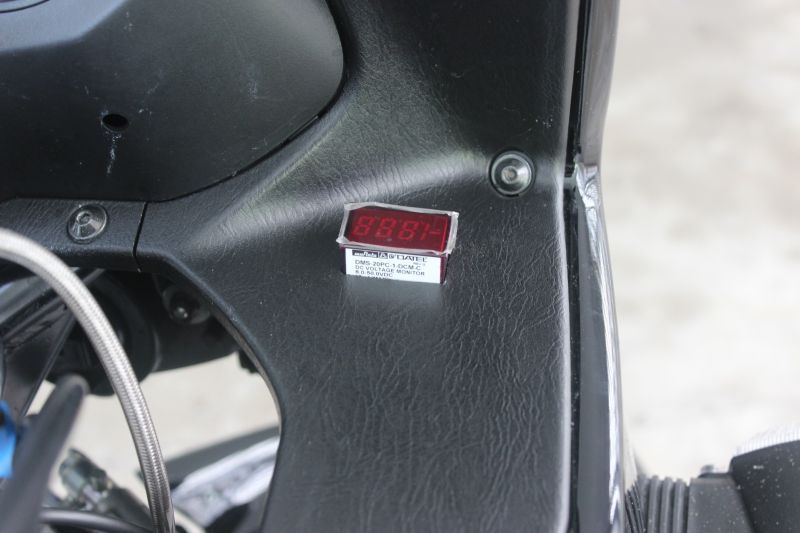
The meter is secured in place by a piece of metal with teeth that slips on from the bottom side. You can get a bezel to go around the top of the meter but it looks it would be a PITA to attach. Besides, I think the flush mount looks better. Note that in this picture the VM is actually upside down. It was taken before hooking it up and securing it.
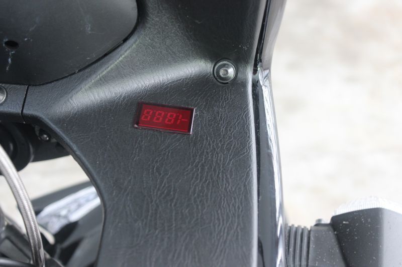
And here it is, installed and functioning. The voltmeter draws very little current to operate so I used 18 or 20 gauge wire and put in a 2 amp fuse at the fuse panel.
III. Electrical Outlets:
The sockets, as well as the plugs that go in them were purchased from Powerlet.com. These items are also known as BMW plugs/sockets.
Sockets: http://www.powerlet.com/product/standard-powerlet-socket/280
Plugs: http://www.powerlet.com/product/basic-plug/275
You might be able to find better prices on these plugs elsewhere. Years ago, someone told me that these very same plugs & sockets could be purchased at John Deere dealerships of all places, for a lot less money.
When thinking about a location for the sockets, I considered drilling a hole in the main, black fairing but later decided to put it in the most rearward position I could find on the gray fairing. It was quite a chore figuring out the best location because there are lot of things underneath the gray fairing in that position. You need to put the socket in a place where the underneath surface of the fairing is flat and not too near anything that could prevent you from tightening the nut that cinches the socket down. It took a lot of back and forth measuring before I felt I had a good spot. In hindsight, it would have been easier if I'd had the fairing off the bike.
The picture below shows how I drilled the hole for the socket using an 11/16" spade bit. IMPORTANT: do this part by hand. Don't use this bit connected to a power tool because you could quickly wind up with a ripped up fairing . Just take your time and turn it by hand.
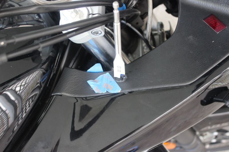
The 11/16" bit I used makes a hole just a tad smaller than the socket so I needed to expand it a bit. For this, I used a small rat tail file. One of those variable sized, step bits would have been better to use I suppose but the spade bit is cheap and is what I had on hand. It worked just fine.
Here are pictures of the final product on the left side. Note that the Powerlet socket has a spring loaded, hinged cap.:
... and the right side:
I used 14 gauge wire to these sockets from the fuse box. Because the left side socket is the one I use to plug for high amp devices such as my heated clothing and air pump, I used a 15 amp fuse at the fuse box for this circuit. The right side is the one I normally use for tank bag electronics which has pretty low current draw so I used a 5 amp fuse.
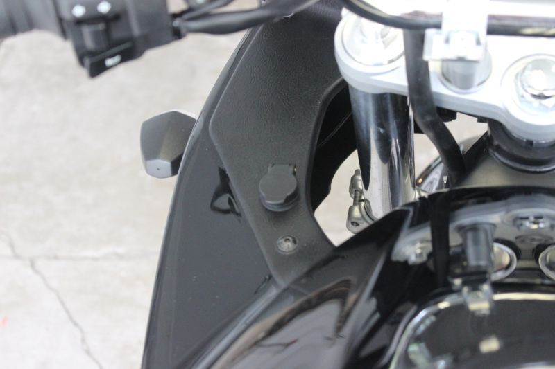
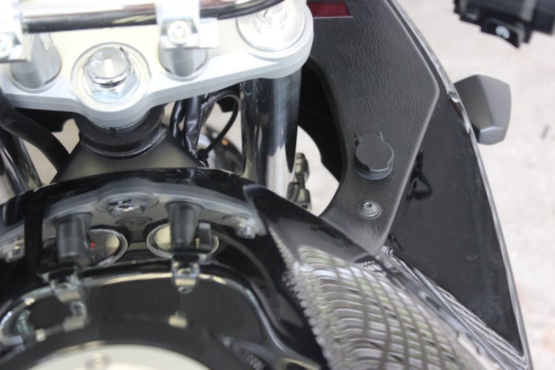
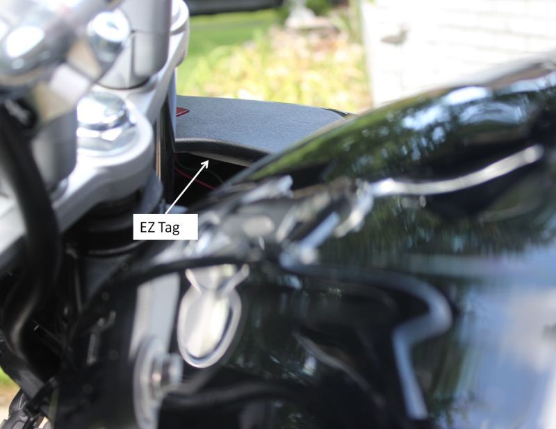
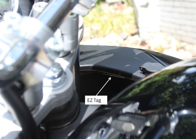
IV. EZ TAG
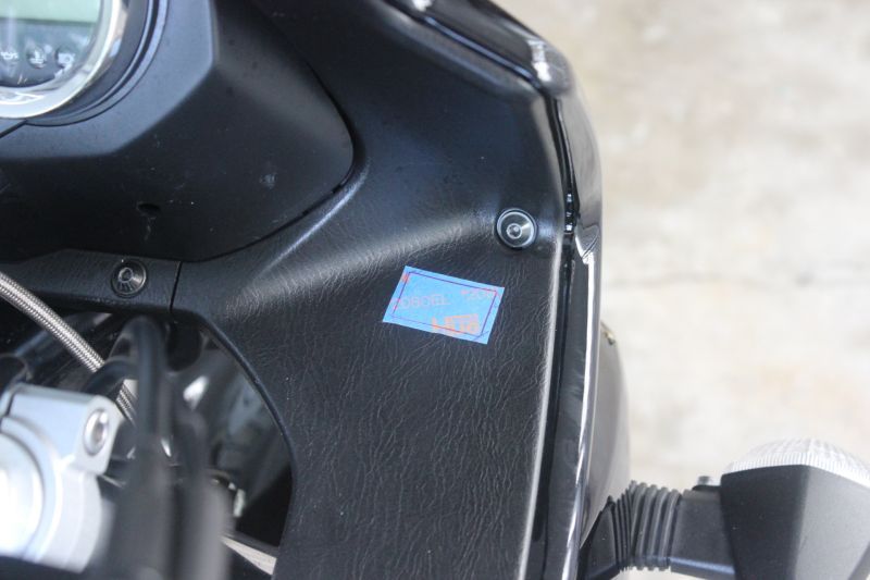
I actually installed this over a year ago but since I've seen posts asking about where to put EZ tags, I thought I'd show pictures of my location.
In Texas, the EZ tags for motorcycles are small, white, rectangular boxes with foam tape already on them. I put mine on the underside of the gray fairing. I've not had any nasty-grams from the toll road authority for not being able to read it so this location works.
The pic below shows that the tag is well hidden. You almost have to know where it is to see it:
To make it is even harder to notice and to make it more securely held, I put black duct tape on it:
V. TRICKLE CHARGER CONNECTION
Since getting this bike, I've just stored the wire for the charger in the battery compartment and pulled it out when I was ready to put the bike away for a while. This was getting old so I decided to find a permanent place on the outside for the "pigtail". The picture below shows where it emerges from beneath the fairing. It's attached with a zip tie. The wiring attachments at the battery were already shown in one of the pictures in the Power Source section.

VI. A NOTE ON WIRE ROUTING:
Unfortunately, I did not take any pictures showing how the wires were routed from the fuse panel to their final destinations. The main thing to keep in mind is to route them so that they do not interfere with anything and don't get pinched, mashed, or burned. Don't skimp on the zip ties. I had to raise the gas tank at the back slightly to be able to guide the wires through and find attachment points for the zip ties. Where the wires ran near the engine, I ran the positive leads through braided plastic conduit to give some added protection to the wire's insulation from the engine heat. This is an example of braided conduit:
http://www.cabletiesandmore.com/ExpandableSleeving.php
It can be purchased at auto parts stores such as Auto Zone.
NOTE: If you'd like to download a pdf of this procedure, click HERE.
*****************************************************************************
A couple of weeks ago I finally got off my duff and installed some electrical farkles on my Bandit. Been wanting to do this for a couple of years but for various reasons, main one of which was just old fashioned procrastination, I never got around to doing it. Finally did the deed. Now I have the ability to use GPS, Radar Detector, plug in air pump, etc. Below are some pics and explanations that will hopefully help out those who wish to do the same.
Here is the list of what I added:
Switched power source for electrical goodies
2 electrical sockets
Exterior mounted trickle charger connection
Voltmeter
EZ Tag
I. POWER SOURCE:
The first order of business was to install the switched power source. So what did I need to accomplish this? The pic below shows the core of what is required. I got these from my local auto parts store, Radio Shack, and Home Depot:
Now to find a location to put all this stuff. There's not a lot of spare room on the Bandit, especially if you want to keep the tool pouch. As it turns out, there's a perfect spot to place a fuse block, relay & ground strip.... under the seat where the owner's manual resides:
I just yanked the manual out and was left with an area that was almost tailor made for placing electrical stuff. I then cut some velcro and applied it inside of the owner's manual storage area:
And here is a picture of these items placed in the owner's manual tray after installation:
A little explanation before proceeding. In order to have switched electrical power to multiple items, it's best to use a relay. The relay activates when the ignition key is turned on. When activated, it supplies power directly from the battery to whatever you want it to go to. In this case, it's going to a 6 circuit fuse panel. From there it goes to whatever you're trying to electrify.
The wire I used from the battery to the relay and from the relay to the fuse block is 12 gauge. That's heavy enough that you don't have to worry about overloading it.
Note the green wire attached to the ground strip. This comes straight from the negative terminal of battery. Like the positive lead, this also is 12 gauge wire. I used green for all ground wires so I wouldn't get them mixed up. Green is the standard color used for ground on every Honda I have ever owned so I thought I'd use that scheme on the Bandit.
How does the relay activate? If you'll look in the upper left corner in the picture above, you'll see a red wire and a red inline tap. This wire is tapped to the license plate light wire and the other end is connected to the relay. When the ignition switch is turned on, the license plate circuit becomes powered up. With the inline tap in place, it then sends juice to the relay which activates, which in turn provides power to the relay's line out terminal directly from the battery.
Below is a close-up picture showing the tap on the license plate light lead (gray wire). This photo is looking directly into the back end of the bike. The light gray area is the shelf where the OEM toolkit is stored.
If you've never dealt with general purpose relays before, you'll be happy to know that they all seem to have a very convenient numbering scheme on the terminals that allow you to hook them up properly. Below is a really great chart that I found on http://www.rattlebars.com/mtz/hornrelay.html . I've also seen this very same chart on other sites:
You can see the terminals that accept wires that come directly from the battery (#'s 85 & 30). As mentioned, I used 12 gauge wire (available at any auto parts store) for both the positive & negative leads. The trigger (coming from the license plate light wire) uses relatively little juice so I used a much thinner 18 gauge wire (runs to terminal 86). For the line out to the fuse block I again used 12 gauge wire.
For attaching the wires to the slip-on terminals, I like to use crimp on,insulated connectors where possible. The insulation reduces the chance of a short. An example of one type can be seen here:
http://www.radioshack.com/product/index.jsp?productId=2104016 . They can be purchased at any number of places such as auto parts stores, radio shack, etc.
Below is a pic showing the wires connected at the battery. Note the yellow colored lead coming off the battery. This is a 12 gauge, fused lead that I bought at my local auto parts store. It is soldered to the red, 12 gauge lead that runs to the relay. The splice is underneath the black split conduit that you see next to the fuse holder on the yellow wire.
II. VOLTMETER:
My voltmeter of choice has always been the Datel from datelmeters.com. They are a bit on the pricey side these days but they are very reliable and waterproof. The model I used was the DMS-20PC-1-DCM:
http://www.datelmeters.com/cgi-bin/webshop.cgi?config=ent-home&uid=udlkbvdc137314370318&command=link--dcvoltmeters.html#2-wire
When installing the Datel, I picked a spot as far forward as possible so that I could see it easier. The final location was chosen such that the voltmeter would sit flush with the fairing and not interfere with anything on the underside.
The tape you see in the picture below is the basic template I used. I traced the outline of the smaller dimension of the VM on a piece of tape. At that point I drilled holes inside NEAR each corner,... not on it or touching it. Note that I drilled these holes by hand.... literally... by taking a drill bit and firmly twisting it slowly. That gray fairing material is relatively soft so it was doable. I had to do this because the fairing curves up and prevents you from getting a drill in there. Once the holes were drilled, I took my trusty Dremel tool and cut out the rectangle. It is important to hold the Dremel firmly and cut slowly because it can get away from you. IMPORTANT: cut along the inside edge of the scribed line, not on it or outside of it. You want the VM to slip in snugly when finished.
Once the initial hole is cut, get it to the exact required size with a small, cross-cut flat file.
The VM should slip in snugly so that no open space is exposed when installed.
The meter is secured in place by a piece of metal with teeth that slips on from the bottom side. You can get a bezel to go around the top of the meter but it looks it would be a PITA to attach. Besides, I think the flush mount looks better. Note that in this picture the VM is actually upside down. It was taken before hooking it up and securing it.
And here it is, installed and functioning. The voltmeter draws very little current to operate so I used 18 or 20 gauge wire and put in a 2 amp fuse at the fuse panel.
III. Electrical Outlets:
The sockets, as well as the plugs that go in them were purchased from Powerlet.com. These items are also known as BMW plugs/sockets.
Sockets: http://www.powerlet.com/product/standard-powerlet-socket/280
Plugs: http://www.powerlet.com/product/basic-plug/275
You might be able to find better prices on these plugs elsewhere. Years ago, someone told me that these very same plugs & sockets could be purchased at John Deere dealerships of all places, for a lot less money.
When thinking about a location for the sockets, I considered drilling a hole in the main, black fairing but later decided to put it in the most rearward position I could find on the gray fairing. It was quite a chore figuring out the best location because there are lot of things underneath the gray fairing in that position. You need to put the socket in a place where the underneath surface of the fairing is flat and not too near anything that could prevent you from tightening the nut that cinches the socket down. It took a lot of back and forth measuring before I felt I had a good spot. In hindsight, it would have been easier if I'd had the fairing off the bike.
The picture below shows how I drilled the hole for the socket using an 11/16" spade bit. IMPORTANT: do this part by hand. Don't use this bit connected to a power tool because you could quickly wind up with a ripped up fairing . Just take your time and turn it by hand.
The 11/16" bit I used makes a hole just a tad smaller than the socket so I needed to expand it a bit. For this, I used a small rat tail file. One of those variable sized, step bits would have been better to use I suppose but the spade bit is cheap and is what I had on hand. It worked just fine.
Here are pictures of the final product on the left side. Note that the Powerlet socket has a spring loaded, hinged cap.:
... and the right side:
I used 14 gauge wire to these sockets from the fuse box. Because the left side socket is the one I use to plug for high amp devices such as my heated clothing and air pump, I used a 15 amp fuse at the fuse box for this circuit. The right side is the one I normally use for tank bag electronics which has pretty low current draw so I used a 5 amp fuse.
IV. EZ TAG
I actually installed this over a year ago but since I've seen posts asking about where to put EZ tags, I thought I'd show pictures of my location.
In Texas, the EZ tags for motorcycles are small, white, rectangular boxes with foam tape already on them. I put mine on the underside of the gray fairing. I've not had any nasty-grams from the toll road authority for not being able to read it so this location works.
The pic below shows that the tag is well hidden. You almost have to know where it is to see it:
To make it is even harder to notice and to make it more securely held, I put black duct tape on it:
V. TRICKLE CHARGER CONNECTION
Since getting this bike, I've just stored the wire for the charger in the battery compartment and pulled it out when I was ready to put the bike away for a while. This was getting old so I decided to find a permanent place on the outside for the "pigtail". The picture below shows where it emerges from beneath the fairing. It's attached with a zip tie. The wiring attachments at the battery were already shown in one of the pictures in the Power Source section.
VI. A NOTE ON WIRE ROUTING:
Unfortunately, I did not take any pictures showing how the wires were routed from the fuse panel to their final destinations. The main thing to keep in mind is to route them so that they do not interfere with anything and don't get pinched, mashed, or burned. Don't skimp on the zip ties. I had to raise the gas tank at the back slightly to be able to guide the wires through and find attachment points for the zip ties. Where the wires ran near the engine, I ran the positive leads through braided plastic conduit to give some added protection to the wire's insulation from the engine heat. This is an example of braided conduit:
http://www.cabletiesandmore.com/ExpandableSleeving.php
It can be purchased at auto parts stores such as Auto Zone.
Last edited: