The color wiring schematic has come through...at least on one part! The reason for the two identical wires is that one runs from the front brake lever and the other runs from the rear brake pedal! Now just to figure out why the voltage is reading wrong. I'm sure it's not the bike...it's me!Just a WAG but it might be to keep the left and right taillights independent and minimize a single-point failure for both lights. The left and right headlights are also wired independent of each other to a point.

Is there an easy way to find the brake light wires?
- Thread starter dc112675
- Start date
That's interesting. Here's a photo of a spare wire harness (I believe to be from a 2005 ST) with the tail/brake lamp conductors configured a bit differently.The reason for the two identical wires is that one runs from the front brake lever and the other runs from the rear brake pedal!
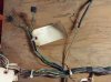
Here you can see that each of the tail/brake lamp connectors (yes, one of the connectors has been altered) only have three conductors. Each of the brake lamp conductors (Green/Yellow) terminate in a connection with two additional Green/Yellow conductors, hidden beneath the Blue taped-up junction, which is buried within the wire harness sheathing. The two additional Green/Yellow conductors are the brake lamp switch conductors; one from the front brake lever switch, and the other from the rear brake pedal switch.
While these two wire harnesses achieve the same electrical results, the methodology is slightly different.
Back to your original question
No, the Black/Brown wire is for the tail lamps.Any ideas where a good place would be. Should I be looking for the brown/wire wire?
If you want to the install the brake light flasher device, such that either the brake lever, or the brake pedal will cause all the brake lamps to flash, then you will need to:
- Determine which two of the four Green/Yellow conductors are the +12vdc from the two brake switches.
- Join these two conductors together.
- Attach the (now joined together) two Green/Yellow conductors to the 'input' terminal of the brake light flasher device.
- The two remaining Green/Yellow conductors will be the individual brake lamp bulb connectors, join these two conductors together.
- Attach the (now joined together) two Green/Yellow conductors to the "output' terminal of the brake light flasher device.
You should now have flashing brake lamps when either the front, the rear, or both brakes are applied.
Thank you so much! I am going to dig back into it this weekend and I'll have a print off of your instructions beside me. Clearly I have only know just enough to be dangerous...in this case that meant pulling off the seat and cutting the wrong wires! Thank you again, dougThat's interesting. Here's a photo of a spare wire harness (I believe to be from a 2005 ST) with the tail/brake lamp conductors configured a bit differently.
Here you can see that each of the tail/brake lamp connectors (yes, one of the connectors has been altered) only have three conductors. Each of the brake lamp conductors (Green/Yellow) terminate in a connection with two additional Green/Yellow conductors, hidden beneath the Blue taped-up junction, which is buried within the wire harness sheathing. The two additional Green/Yellow conductors are the brake lamp switch conductors; one from the front brake lever switch, and the other from the rear brake pedal switch.
While these two wire harnesses achieve the same electrical results, the methodology is slightly different.
Back to your original questionNo, the Black/Brown wire is for the tail lamps.
If you want to the install the brake light flasher device, such that either the brake lever, or the brake pedal will cause all the brake lamps to flash, then you will need to:
If the brake lamp flasher device requires a "on with ignition" connection to +12vdc, you might consider using the Black/Brown (tail lamp) conductor as a source.
- Determine which two of the four Green/Yellow conductors are the +12vdc from the two brake switches.
- Join these two conductors together.
- Attach the (now joined together) two Green/Yellow conductors to the 'input' terminal of the brake light flasher device.
- The two remaining Green/Yellow conductors will be the individual brake lamp bulb connectors, join these two conductors together.
- Attach the (now joined together) two Green/Yellow conductors to the "output' terminal of the brake light flasher device.
You should now have flashing brake lamps when either the front, the rear, or both brakes are applied.