- Joined
- Mar 18, 2006
- Messages
- 2,824
- Age
- 70
- Location
- Ilkley, W Yorkshire, UK
- Bike
- 2013 ST1300 A9
- 2024 Miles
- 000679
- STOC #
- 2570
This isn't a new idea and has been mentioned before in these forums. But when I needed it, I couldn't find what I was looking for in one place.
A (very expensive) addition to the Honda top box is the colour matched spoiler. It comes complete with a row of high intensity Red LEDs which are plumbed into the brake light circuit. High level brake lights are now a legal requirement for all new cars in the UK. They are a pretty good idea on the ST1300 too.
However, if you have ever followed another ST1300 in poor daylight, you soon realise how poor the rear lights are. This little modification converts the LED brake lights into a tail/stop light. It requires a few electronic components - 2 diodes (or rectifiers) and a resisitor, some wire and (optional) a couple of electrical connectors.
The idea is to feed the LEDs with two power inputs. One from the brake light circuit, another from the tail light circuit, but at a reduced voltage. The diodes are there to prevent the power from the brake light circuit flowing into the tail light circuit and vice versa.
It took a little experimenting to get a resistor of the right value. The tail light mustn't be too bright, or it won't be possible to tell when the brake light comes on. Too dim, and there is no point in having it !
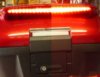
A split image - left side showing the tail light, right side showing the brake light.
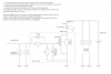
Circuit diagram The 3 wires from the left are tapped into the 3 leads going to the tail stop light.
Green = Earth
Brown = Tail Light
Yellow / Green = Brake light
Please check the colours of the leads to your tail light rather than relying on the ones shown here.
The two wires on the right go to the LED brake light.
The two diodes are 1N5400 - more than big enough for the job
The resistor is 220 ohm, 7 watts. Again, I've gone for overkill.
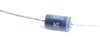
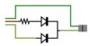
The photos above shows the components laid out on the circuit diagram. The second photo of the diode shows the orientation - that grey stripe at the end is in the same location as indicated by the black bar on the diagram - in this case pointing to the right.
Note the white 2-pin connector on the right is designed to fit into the connector provided with the Honda spoiler. Check that the colours of the wires match before connecting together.
The green connector on the left is optional. There is nothing to plug it into unless you put the female part in place yourself. The alternative is to hard wire it in place. I prefer to have connectors - it makes it easier to replace the module if necessary. In fact, in the event of failure, I have a simple lead which connects the green connector to the white to reinstate the LED as a standard brake light. And I made two of these modules so that if one fails, the other can be plugged in to replace it.
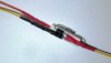
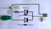
A shot showing how I wired this up. The size of the resistor in its hard rectangular ceramic case makes a sturdy device to which the diodes can be secured. The diodes were taped to the resistor and the ensemble was then put into a length of 3.5cm wide heat shrink tubing and effectively shrink-wrapped - leaving two wires at one end, 3 wires at the other. This does not show the green earth wire which simply passes from one side to the other. Neither does it show the connectors.
I didn't have the correct colour wire at hand. The orange lead is the one from the +ve tail light circuit (brown on the diagram). The yellow lead is the one from the +ve brake light circuit (yellow / green on the diagram). That dark grey looking lead on the right alongside the yellow is actually a shadow from the flash !
I didn't take a photo of the finished component. Next time I'm delving in the rear cowl, I'll take it out and take a shot to complete the story.
To get at the wiring for the tail stop light, remove the rear mudflap - 4 bolts. The rear light holders can be removed (best to undo both sides. The right lamp holder is connected to the wiring loom, the left is connected to the right. I found that there was more wiring to play with on the right hand bulb holder. Best to remove the bulbs (don't touch with fingers), otherwise you risk breaking them and kneeling on the broken glass. If you decide to cut and crimp on new connectors, make sure you have enough length of wire to operate the crimp pliers. You might need to work closer to the bulb holder than you would prefer.
NB - Make absolutely certain that you have the diodes facing in the correct direction - that grey band must face in the direction of the LED wire. Also make certain that the connector wires are in their correct place.
In the UK, Hitachi connectors can be found at SG Motorsports.
In USA this is one supplier mentioned in a different post http://www.electricalconnection.com/
Diodes and resistors bought over the internet from Maplins (UK)
A (very expensive) addition to the Honda top box is the colour matched spoiler. It comes complete with a row of high intensity Red LEDs which are plumbed into the brake light circuit. High level brake lights are now a legal requirement for all new cars in the UK. They are a pretty good idea on the ST1300 too.
However, if you have ever followed another ST1300 in poor daylight, you soon realise how poor the rear lights are. This little modification converts the LED brake lights into a tail/stop light. It requires a few electronic components - 2 diodes (or rectifiers) and a resisitor, some wire and (optional) a couple of electrical connectors.
The idea is to feed the LEDs with two power inputs. One from the brake light circuit, another from the tail light circuit, but at a reduced voltage. The diodes are there to prevent the power from the brake light circuit flowing into the tail light circuit and vice versa.
It took a little experimenting to get a resistor of the right value. The tail light mustn't be too bright, or it won't be possible to tell when the brake light comes on. Too dim, and there is no point in having it !
A split image - left side showing the tail light, right side showing the brake light.
Circuit diagram The 3 wires from the left are tapped into the 3 leads going to the tail stop light.
Green = Earth
Brown = Tail Light
Yellow / Green = Brake light
Please check the colours of the leads to your tail light rather than relying on the ones shown here.
The two wires on the right go to the LED brake light.
The two diodes are 1N5400 - more than big enough for the job
The resistor is 220 ohm, 7 watts. Again, I've gone for overkill.
The photos above shows the components laid out on the circuit diagram. The second photo of the diode shows the orientation - that grey stripe at the end is in the same location as indicated by the black bar on the diagram - in this case pointing to the right.
Note the white 2-pin connector on the right is designed to fit into the connector provided with the Honda spoiler. Check that the colours of the wires match before connecting together.
The green connector on the left is optional. There is nothing to plug it into unless you put the female part in place yourself. The alternative is to hard wire it in place. I prefer to have connectors - it makes it easier to replace the module if necessary. In fact, in the event of failure, I have a simple lead which connects the green connector to the white to reinstate the LED as a standard brake light. And I made two of these modules so that if one fails, the other can be plugged in to replace it.
A shot showing how I wired this up. The size of the resistor in its hard rectangular ceramic case makes a sturdy device to which the diodes can be secured. The diodes were taped to the resistor and the ensemble was then put into a length of 3.5cm wide heat shrink tubing and effectively shrink-wrapped - leaving two wires at one end, 3 wires at the other. This does not show the green earth wire which simply passes from one side to the other. Neither does it show the connectors.
I didn't have the correct colour wire at hand. The orange lead is the one from the +ve tail light circuit (brown on the diagram). The yellow lead is the one from the +ve brake light circuit (yellow / green on the diagram). That dark grey looking lead on the right alongside the yellow is actually a shadow from the flash !
I didn't take a photo of the finished component. Next time I'm delving in the rear cowl, I'll take it out and take a shot to complete the story.
To get at the wiring for the tail stop light, remove the rear mudflap - 4 bolts. The rear light holders can be removed (best to undo both sides. The right lamp holder is connected to the wiring loom, the left is connected to the right. I found that there was more wiring to play with on the right hand bulb holder. Best to remove the bulbs (don't touch with fingers), otherwise you risk breaking them and kneeling on the broken glass. If you decide to cut and crimp on new connectors, make sure you have enough length of wire to operate the crimp pliers. You might need to work closer to the bulb holder than you would prefer.
NB - Make absolutely certain that you have the diodes facing in the correct direction - that grey band must face in the direction of the LED wire. Also make certain that the connector wires are in their correct place.
In the UK, Hitachi connectors can be found at SG Motorsports.
In USA this is one supplier mentioned in a different post http://www.electricalconnection.com/
Diodes and resistors bought over the internet from Maplins (UK)
Last edited: