Who understands the PAIR system to know I can clamp it off, leaving it in place?

OP
OP
moddy

moddy

the mod
Joined
Dec 2, 2011
Messages
836
Location
Seymour, IN
Bike
05 ST1300
STOC #
8843
Just two thoughts -

1. Could the cruise control 'brain' be faulty?
This is a good question. Luckily I have had 2 servos to compare, and close to the same symptoms of same behavior between the two.
Fortunately, Blayde was willing to ride my bike and engage the cruise himself. This was very helpful as he rode over to help on a KLR that has it installed. I also got to ride his KLR as a first time on one and to see what riding one with a working Audiovox CC was like.

2. Could the cable be binding/too hard to pull and cause the 'brain' to stop pulling the cable?
That cable moves in and out very nicely. No friction. It feels and looks they way it should operate. I also copied John O's routing.
As I mentioned in a previous post, there are sections of vac tubing I've found to have an issue with the inner wall. Conducting a vac integrity test at the moment.
 

Uncle Phil

Site Supporter
Joined
Feb 26, 2007
Messages
11,301
Age
71
Location
In The Holler West Of Nashville, Tennessee
Bike
4 ST1100(s)
2024 Miles
002064
STOC #
698
Since I'm not familiar with the Audiovox, my reference is the MCCruise which has the vacuum servo and then the 'brain' that communicates with the servo. Is the Audiovox an 'all in one unit'? Or are the electronics separate from the servo? I know the Rostra unit is an 'all in one unit'.
 
OP
OP
moddy

moddy

the mod
Joined
Dec 2, 2011
Messages
836
Location
Seymour, IN
Bike
05 ST1300
STOC #
8843
Since I'm not familiar with the Audiovox, my reference is the MCCruise which has the vacuum servo and then the 'brain' that communicates with the servo. Is the Audiovox an 'all in one unit'? Or are the electronics separate from the servo? I know the Rostra unit is an 'all in one unit'.
Yes, the Audiovox is an all in one unit. The wire harness connects to ground, a positive source and a wire to "brake lights on" wire that disconnects the cruise should the brakes be applied.
 

John OoSTerhuis

Life Is Good!
Joined
May 10, 2005
Messages
5,221
Location
Bettendorf, Iowa
Bike
1991 SSMST1100
STOC #
1058
At this point I'd replace the tail lights with OEM incandescents (which work better with the OEM reflector anyway), and connect the CC rear brake wires per my install. Seriously. This has to be the source after all you've done/checked.... JMHO of course.

John
 
Last edited:
OP
OP
moddy

moddy

the mod
Joined
Dec 2, 2011
Messages
836
Location
Seymour, IN
Bike
05 ST1300
STOC #
8843
At this point I'd replace the tail lights with OEM incandescents (which work better with the OEM reflector anyway), and connect the CC rear brake wires per my install. Seriously. This has to be the source after all you've done/checked.... JMHO of course.

John
Hi John. I think mentioning there were LED's involved at all was unnecessarily confusing. I tied a 24" LED strip to come on with the circuit for when incandescence come on, and the wire for disconnecting CC will be tied into the OEM "brake lights on" wire. Nothing to do with LED circuits. Looking forward to my test ride again, having cut out all of the compromised vac tubing.
 

John OoSTerhuis

Life Is Good!
Joined
May 10, 2005
Messages
5,221
Location
Bettendorf, Iowa
Bike
1991 SSMST1100
STOC #
1058
Hi John. I think mentioning there were LED's involved at all was unnecessarily confusing. I tied a 24" LED strip to come on with the circuit for when incandescence come on, and the wire for disconnecting CC will be tied into the OEM "brake lights on" wire. Nothing to do with LED circuits. Looking forward to my test ride again, having cut out all of the compromised vac tubing.
Hmm... try disconnecting the LEDs completely anyway. What can it hurt at this point? And hook up the CC rear brake sensing wires like they’re supposed to be. Not quite sure I understand your grounding the purple wire idea... hook it up correctly. JMO

FWIW, If I had installed an LED strip it would be on a relay.

John
 
OP
OP
moddy

moddy

the mod
Joined
Dec 2, 2011
Messages
836
Location
Seymour, IN
Bike
05 ST1300
STOC #
8843
Hmm... try disconnecting the LEDs completely anyway. What can it hurt at this point? And hook up the CC rear brake sensing wires like they're supposed to be. Not quite sure I understand your grounding the purple wire idea... hook it up correctly. JMO

FWIW, If I had installed an LED strip it would be on a relay.

John
If you didn't know, the purple wire without being connected to anything is +12v and cruise will not engage. It will also not engage if it senses too much voltage while properly connected to the "brake lights on" wire. I don't know how much voltage this is, so while my cruise has yet to stay engaged for whatever reason, to rule out an over voltage in that wire, that some people use a relay to ground because the have LED brake lights, I have the purple wire grounded to the frame to insure that is not why it won't engage. It's only temporary. When the CC finally joins the party, I will connect the brake light sensor wire.
 
OP
OP
moddy

moddy

the mod
Joined
Dec 2, 2011
Messages
836
Location
Seymour, IN
Bike
05 ST1300
STOC #
8843
JTBC - thatÂ’s CC brake sensor wires... plural.
My reference is to the purple wire not being connected. So I chose a singular context. The servo's red wire has always been connected to the "brake lights constant on" wire, as shown in your pictures that shows the servo's red wire connection to your brake wire circuit.
I've read through your write up...again. And what I'm looking for an answer to, I can't find. You make no mention of where the servo's orange wire is connected and it could be the answer to this functioning properly, since every other wire on my servo is connected where you did, and yours works.
This whole time, I've had it connected to a wire that has no power when the key is off, but when the key is on it has +12volts, even through cranking, because the orange wire is powered by a connection made with a relayed Blue Sea 6 buss fuse block. It is not a wire that is 0 volts when the engine is cranking, this could be the issue.
This could be the nuance in the circuitry that is not allowing it to operate successfully.
Per instructions, it says "Connect the Orange wire from the fuseholder to a wire in the vehicle that shows + 12 VDC when the ignition key is switched On and 0 VDC while cranking and when the key is switched OFF."
Since Blayde stopped by 4 days ago I have been going over the symptoms of all the test rides. How it behaved when I tried to engage it, followed by it's 1/2 second later disconnection every time.

SIDE NOTE, this is not the behavior of the first servo. At slower speeds 30 to 40 mph the cruise would stay engaged. The new servo is more stubborn to get anything out of than the first one, the older one, SIDE NOTE CONCLUDED.

From the symptoms of why it would disconnect and how, believing the vacuum to have good integrity, have aimed my attention toward an electrical wiring problem. Before Blayde left, not understanding why it wasn't simpler, said the default to it not working properly, is to not work at all. This is obvious, because it deals with being connected to your throttle body. If it detects something wrong with the way you've wired it or your source of vacuum is insufficient, no worky.
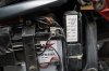
We had the cover of the servo off and watched the LED light up with every button press. With the engine running from idle to 4500rpm the LED blinks successively faster, blue sensing wire is sensing as it should, good soldered connection.
Most importantly from the marathon of tests last Saturday was each time I pressed set or resume there was a strong initial pull on the throttle, I have vacuum and it doesn't leak. As a reminder the supplemented pvc vac container is about 8 inches by 1 1/2 inches in diameter. In the least, on flat ground should have the vacuum assist necessary to maintain speed.
 
Last edited:
OP
OP
moddy

moddy

the mod
Joined
Dec 2, 2011
Messages
836
Location
Seymour, IN
Bike
05 ST1300
STOC #
8843
I suspect that that there's a fault in the wiring that feeds the brake switch...this should clear it up and guarantee that it's not from the brake light circuit. http://valkyrieriders.com/shoptalk/cruise_files/relay5_diag1.gif 1/10 of a volt should not be enough to effect proper relay function.....the hope this helps.
There is only one problem with what would normally be the brake lights on connection, the purple wire is grounded at the moment. Which means, my cruise control system will not disconnect by applying the brakes. Cruise control has not stayed engaged longer than 2 minutes, and long ago needed to rule out the possibility too much voltage was being sensed in the brake lights on wire, while trying to figure out why it wouldn't stay engaged. I need to find out where anyone who has a working audiovox cruise control system has connected their orange wire.
 
Last edited:
Joined
Apr 7, 2007
Messages
624
Location
Tacoma, wa
sorry bout that...I missed that you have the purple wire already grounded, as I suggested way back . I have installed two of these but never employed the factory key pad. the orange wire ( from the keypad), is connected to a 12volt switched source- like the bikes running/position lights. as I remember it, the orange wire only provides 12volt to power the led key pad back light feature and either caped off or connected, will not effect cc function. fwiw- I've noticed that the installation of a "noise suppressor" on the coil pick up wire appears quite often in generic cc100 installations/wiring diagrams on line- I have no experience with these devices. hope this helps
 
Last edited:
OP
OP
moddy

moddy

the mod
Joined
Dec 2, 2011
Messages
836
Location
Seymour, IN
Bike
05 ST1300
STOC #
8843
sorry bout that...I missed that you have the purple wire already grounded, as I suggested way back . I have installed two of these but never employed the factory key pad. the orange wire ( from the keypad), is connected to a 12volt switched source- like the bikes running/position lights. as I remember it, the orange wire only provides 12volt to power the led key pad back light feature and either caped off or connected, will not effect cc function. I've noticed that the installation of a "noise suppressor" on the coil pick up wire appears quite often in generic cc100 installations/wiring diagrams on line- I have no experience with these devices. hope this helps
Unfortunately, it will take some time get to this. Appreciate the help.
 

John OoSTerhuis

Life Is Good!
Joined
May 10, 2005
Messages
5,221
Location
Bettendorf, Iowa
Bike
1991 SSMST1100
STOC #
1058
David. It’s been a loooong time since my install. I’m fighting another serious bout of back pain (second steroid injection next week) so I’m not up to pulling Tupperware to see, but IIRC I discarded the orange wire inline fuse provided and installed a nice waterproof one instead and hooked it up to a switched source. Works fine, but if you’re concerned, tap into the headlight circuit as they are cut off when the start switch is depressed.

Humor me and unplug the LED bar.

John
 
Last edited:
OP
OP
moddy

moddy

the mod
Joined
Dec 2, 2011
Messages
836
Location
Seymour, IN
Bike
05 ST1300
STOC #
8843
I will unplug the LEDs. Hope your back gets better soon. Will advise when test is complete.
 
OP
OP
moddy

moddy

the mod
Joined
Dec 2, 2011
Messages
836
Location
Seymour, IN
Bike
05 ST1300
STOC #
8843
While all of these previous posts are going on in my head and still testing to do, I collected this statement while researching cruise control types and installation options.
dalelive, finally a successful install.JPG

While I am working out a possibility the orange wire, by instructions, is installed on a wire that is on, except while cranking, then provides +12V and the red wire that is connected to the brake system wire that is on (brake lights running light)? It just interested my there were two sources of +12volts for the system. Now, I found the above excerpt well before installation, I just rediscovered it in a folder I'd been keeping of saved pictures and notes before I started. I checked the red wire, brake lights running lights connection and orange wire connection and had +13 volts. So I don't think I'm experiencing a system shortfall in power. I don't know when I will get to this again. I have to be in Louisiana for 10 days soon, then 2 1/2 weeks later will be there again. I don't have somewhere to work on it outside, so it could be sometime before I get to this again. Thanks for the help. You will be sure to know what happens when it does.
 
OP
OP
moddy

moddy

the mod
Joined
Dec 2, 2011
Messages
836
Location
Seymour, IN
Bike
05 ST1300
STOC #
8843
1.jpg2.jpg3.jpgI attached orange wire to red wire as shown. Red wire goes to fusebox above battery
Thank you for the effort in tearing down your bike for the pictures. So the orange wire is hooked up to +12v continuously?
 
Joined
Jun 2, 2013
Messages
16
Location
helena, MT
Bike
'97 ST1100
Thank you for the effort in tearing down your bike for the pictures. So the orange wire is hooked up to +12v continuously?


I just checked that with tester. The red wire comes on with the switch on. It is not live with the switch off. Are the photos clear enough? You can click on them individually. I hope this helps?
 
Top Bottom