The operation of a hydraulic master cylinder - as used for the front brake lever, rear brake pedal, clutch lever and SMC. Coloured diagrams and explanations.
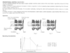
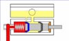
1 - 'Relaxed' Brake Master Cylinder (ie Brakes are not Applied)
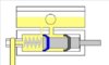
The image shows the front master cylinder and the reservoir immediately above it - just like the ones used on the clutch and brake lever on the ST1300. The piston and push rod are shown in grey.
The primary seal (blue) is the one that applies considerable pressure to the braking system.
The secondary seal (black) maintains a body of fluid behind the primary seal which is gravity fed from the reservoir above. It also isolates the system from the outside world. This seal is never normally put under any great (ie braking force) pressure. The ST1300s secondary master cylinder being an exception to this arrangement - being fed from the rear pedal master cylinder.
Note the larger inlet port between the reservoir and the piston/cylinder. This maintains a volume of fluid between the two seals, fed constantly from the reservoir. The inlet port is never closed off by the position of the piston and seals.
The tiny compensating port is immediately in front (just to the left) of the primary seal. This allows fluid in the braking system to return into the reservoir and relieves any build up of pressure when the braking system is in this 'relaxed' state.
The spring is responsible for returning the piston to the right on this diagram. The push rod at the right hand end is operated by the brake lever.
The hose to the brake calliper is shown descending beyond the bottom of the picture on the left of the master cylinder.
----------------------------------------------------------------------
2 - Master Cylinder when Brake is Applied
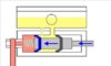
In Diagram 2, the piston has been pushed to the left. Fluid under pressure (pink) is forced down the brake line to the pistons in the brake calliper. Note that the primary seal (blue) has moved past the compensating port, preventing any fluid from returning to the reservoir. The fluid under pressure is responsible for pushing out the pistons in the brake calliper which push the brake pads onto the disc rotors. Once the brake pads are in contact with the disc rotors it takes only a small movement in the master cylinder (brake lever) to exert a force sufficient to bring the bike to a halt.
----------------------------------------------------------------------
3 - Releasing the Brake Lever
(now showing the correct diagram - thanks Midlife)
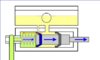
When the brake lever is released, the piston and plunger are returned to the initial 'relaxed' position primarily as a result of the spring pressure in the master cylinder, but aided by the flexible hoses and the calliper piston seals returning to their normal state.
Each time the brakes are applied, the pads wear down a tiny fraction, and the calliper pistons are pushed out further than they were before the brakes were applied. When the brakes are released, the spring returns the master cylinder piston to its relaxed state and a negative pressure (vacuum) is created in the brake lines. Fluid is able to flow past the lips of the primary seal to allow for the fact that the pads have worn down a little.
The primary seal yields easily as the piston moves back - behaviour that is perfectly normal in exactly the same way that the seal in a bicycle pump gives way to allow air to get back into the tube on the upstroke.
The diagram shows the piston towards the end of its travel back to its 'relaxed' state, and the red arrow indicates the flow of extra fluid from the yellow reservoir fluid and into the brake lines (green fluid).
----------------------------------------------------------------------
4 - Dealing with Pressure Build-up
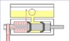
When the brake is not being applied, and the system is in a relaxed state, it is important that fluid is able to 'flow' to and from the reservoir as required. This is can happen when:-
* A slight warps in the disc rotors or general chattering of the brakes over bumpy surfaces pushes the pistons in slightly.
* An increases in temperature causes the fluid to expand.
* The bike cools down in the garage overnight and the fluid contracts. The relief port allows fluid to flow into the brake lines rather than suck the calliper pistons back.
* The brake pads are replaced and the calliper pistons are pushed in. The displaced fluid returns to the reservoir through the tiny relief port. No damage can result in pushing in the calliper pistons in this way if the system has been flushed with new fluid and the exposed calliper pistons are clean. Otherwise it is better to expel the old fluid from the calliper bores via the bleed valve.
The picture shows the pressure in the brake line being allowed to pass through the tiny compensating port into the reservoir, once the brake lever has been released. To prevent the 'fountain' shown in the diagram, a small chromed disc clips slightly above the port at the bottom of the reservoir.
----------------------------------------------------------------------
5 - Blocked Pressure Relief Port
If the piston is prevented from returning to its proper 'relaxed' state, then the Primary Seal will not expose the tiny compensating port. This could be caused by corrosion behind the piston, as shown. This part of the piston is open to the elements unless treated with silicone grease and covered with a rubber boot.
Alternatively, the compensating port itself could be blocked. Fluid that isn't replaced every year can turn into a thick gel which accumulates in the bottom of the reservoir. Or perhaps debris has fallen into the reservoir during a service.
Whatever, if the compensating port is not clear, or the piston fails to return properly to expose the compensating port, pressure builds up (red) and the brakes lock on solid. I have seen one situation recently where a master cylinder service kit was supplied incorrectly. The push rod was slightly too long and front brakes locked on solid at the first application and would not release.
----------------------------------------------------------------------
The illustrations refer to the ST1300 front master cylinder, but the principles also apply to the secondary master cylinder and the rear master cylinder, even though their relief port is connected to the fluid inlet line rather than to the reservoir itself.
-----------------------------------------------------------------------
Final note. Throughout this document, I have made much more of the role of the compensating port in relieving pressure than its other functions.
In fact, the port will allow fluid to flow in either direction to add or remove fluid from the lines to compensate for the fact that the existing fluid will expand or c
ontract as the temperature fluctuates. To do this, the master cylinder piston has to be returned to its relaxed position so that the port is not blocked by the seal. The spring in the master cylinder ensures that this happens.
-------------------------------------------------------------------------
Edit July 2020
There is an excellent discussion below, from which I accientally removed my contributions in a cleanup operation. Don't ask! Fortunately, other members have quoted my missing replies, so the gist of that discussion still makes sense If those quotes are read.