Battery not charging problem

Joined
Jun 3, 2006
Messages
3,518
Location
British Columbia
Bike
2021 RE Meteor 350
Here's something else Bob.

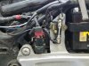
If you are lucky enough for it to be just the VRR, you need to inspect that wiring into the 6P VRR connector closely. Do you see any signs of overheating in the plastic? If so, it will be yellowish/brown, particularly where the larger red wire goes into the connector. That red wire carries all the current flowing from the VRR to the battery and if your bike has a number of electrical farkles on it, it can lead to peak demand from the alternator all the time, causing that wire to overheat and corrode and build up resistance in the connector. More resistance equals more heat.

In serious overheating cases, the plastic will start to melt. My belief about the large number of 28 amp stator failures we have seen over the years, lies in that fact that the 28 amp system only has about 10 amps to spare, after the stock bike's systems are supplied and farkling the bike up with extra driving lights, louder horns, heated riding gear, etc, simply burns the life out of the alternator.

If the red wire to the VRR looks burned at all, you should cut it back to clean wire (you may need to add a piece of wire to it), however, getting that spade connector out of the plastic housing requires a special tool and that spade IS a different size than the others in there and is not easy to find.
 
Last edited:
Joined
Jun 3, 2006
Messages
3,518
Location
British Columbia
Bike
2021 RE Meteor 350
On the alternaor side dead shorts on all 3 pins.
This is where I think you went wrong on this test. If you place the probes from the ohmmeter between the yellow wires, you will see a reading between each of the three yellow wires going to the alternator - 0 to 1 ohm is normal. What you want to ascertain is that none of those coils is shorted to ground. Put one probe on each yellow wire, while the other probe is grounded to the battery negative. There should be no connection - no reading.
 

John OoSTerhuis

Life Is Good!
Joined
May 10, 2005
Messages
5,224
Location
Bettendorf, Iowa
Bike
1991 SSMST1100
STOC #
1058
No email from you yet.

What does the white 6P connector that plugs into the VRR look like? Any evidence of overheating? Corrosion? Any damage on the VRR itself? Check the resistance in the three yellow leads between the red 3P and white 6P.

Edit: I see Forest (Bush) posted while I was composing...
There should be no connection - no reading.
Or read/display infinite resistance (infinity symbol) depending on your multimeter/setting.

My friend just asked me for your contact info... Click on my name above the avatar picture and select email.

John
 
Last edited:

moddy

the mod
Joined
Dec 2, 2011
Messages
836
Location
Seymour, IN
Bike
05 ST1300
STOC #
8843
This is where I think you went wrong on this test. If you place the probes from the ohmmeter between the yellow wires, you will see a reading between each of the three yellow wires going to the alternator - 0 to 1 ohm is normal. What you want to ascertain is that none of those coils is shorted to ground. Put one probe on each yellow wire, while the other probe is grounded to the battery negative. There should be no connection - no reading.
Bob is going by a manual or previously posted parameters with a voltmeter? When set to continuity at the p3 connector, they are supposed to short. They are soldered together in series, inside the stator. Having disassembled my 28A stator recently, I found the solder joints fail under the the black connector. I have since soldered them and resealed, bench tested and all parameters pass whether ohm or continuity. What will I do with it? Waiting for someone in Europe who would quite like to run one of those. Less exposed to the elements.
 
Joined
Mar 13, 2012
Messages
5,066
Location
soCal
Bike
'97 ST1100
STOC #
687
Here's the entire page, which includes some resistance measurements for the VRR, which may be helpful.

For the VRR measurement, note the polarity of the leads shown in the table, this is necessary because the diodes will conduct in one polarity and not the other. If you reverse the leads from that shown in the table the results are invalid.

Also, some multimeters have a resistance setting and a diode setting, both measure resistance but the diode setting produces enough voltage across the leads to forward bias the diode. I don't have any experience with this specific test, so I'm not sure if either setting produces the same result or if you'd need the diode setting to get it to measure correctly.

alternator.jpg
 
Last edited:

John OoSTerhuis

Life Is Good!
Joined
May 10, 2005
Messages
5,224
Location
Bettendorf, Iowa
Bike
1991 SSMST1100
STOC #
1058
If anyone has successfully checked a VRR using these instructions please post and identify the multimeter you used. I've never heard of anyone doing this... always completely erroneous readings, even on a new/good one. I've never heard of anyone having the meters spec'd in the manual. The only way we've come up with over all these years to confirm a damaged VRR is to do a controlled substitution with a known-good VRR. FWIW

John
 
Last edited:

moddy

the mod
Joined
Dec 2, 2011
Messages
836
Location
Seymour, IN
Bike
05 ST1300
STOC #
8843
These are my thoughts as well. Have not tested a vrr separately from the bike. Maybe there are some test parameters somewhere. The vrr is a series diodes, far as I know. Pretty expensive one brand new.
 
OP
OP
robertp039
Joined
Feb 6, 2017
Messages
35
Location
Grove City PA
Bike
Honda ST1100
A big shout out to Tom and John trying to figure out why my battery is not charging?? Still have the problem and I am going to try and clean up some oil around the alternator. You guys are awesome!

Bob
 
OP
OP
robertp039
Joined
Feb 6, 2017
Messages
35
Location
Grove City PA
Bike
Honda ST1100
If it is my alternator does anyone have one that they would sell me. Thanks Robert Pemrich 724.968.2235

Thanks Bob
 
Joined
Aug 26, 2013
Messages
115
Location
Dewitt, Michigan
Bike
1997 ST1100
Another common electrical fault is the starter relay connector. Check to see if it is melted or deformed. It's the red plug next to the main system fuse to the lower right of the battery. If this connector is bad, you will experience all sorts of starting problems.Starter_Relay2.jpg
 
OP
OP
robertp039
Joined
Feb 6, 2017
Messages
35
Location
Grove City PA
Bike
Honda ST1100
Another common electrical fault is the starter relay connector. Check to see if it is melted or deformed. It's the red plug next to the main system fuse to the lower right of the battery. If this connector is bad, you will experience all sorts of starting problems.Starter_Relay2.jpg
Thanks, I I checked mine and it looks good.
 
OP
OP
robertp039
Joined
Feb 6, 2017
Messages
35
Location
Grove City PA
Bike
Honda ST1100
Well, I had I thought I had it fixed. After I cleaned up the connections it was testing good. It was showing 13.50 to 1400 volts to the battery when running. But that was with the headlight fuse out. As soon as I put it back in it was only reading around 12.45 to 12.65 running. Getting frustrated with this now. Does anyone have a alt they want to sell me??
 
Joined
Jul 18, 2012
Messages
48
Location
NJ
STOC #
8924
Robert your reported testing results are inconsistent and contradictory so I can't analyze the problem. Did you try that $15 regulator? May very well solve your problem.
 
OP
OP
robertp039
Joined
Feb 6, 2017
Messages
35
Location
Grove City PA
Bike
Honda ST1100
Robert your reported testing results are inconsistent and contradictory so I can't analyze the problem. Did you try that $15 regulator? May very well solve your problem.
Yes, I bought the regulator and when that is installed I get no charge to the battery. Put the old one back in and I am getting about 14.10 putting the engine up to about 5k. But that is without the headlight fuse in. I am now getting a reading of 0.00 on the test that I put red lead on Alt yellow wire and black to ground. The other test I'm getting 20.0 on all three yellow wires when the engine is running. I figure the vrr I bought is bad and maybe it still is the VRR?? At least I can ride in the daylight. lol

Thanks
Bob
 
Joined
Jul 18, 2012
Messages
48
Location
NJ
STOC #
8924
I was following the thread but you never mentioned the VRR again. You might be able to get a VRR from a forum member who has done 40 Amp upgrade to verify your results. In the event that it is the alternator, seems so, you will not need the entire alternator, just the stator goes bad, the mechanical drive parts are very durable. I got a used 28 Amp from a forum member it fixed my no charge condition. It is quite a laborious task to swap though. Good Luck!
 

moddy

the mod
Joined
Dec 2, 2011
Messages
836
Location
Seymour, IN
Bike
05 ST1300
STOC #
8843
There is a check for resistance and continuity on the alt side, before you do anything else, it's also an easily accessible test, only disconnecting the p-2 and p-3 connectors. Believe me when I tell you, if you go through the hassle of replacing the alternator, only to have the same symptoms isn't worth the time and frustration until the direction you need to go is diagnosed.
Back to the continuity and resistance test, p-2 and p-3 disconnected, voltmeter set to continuity.
It should chirp with any of the 3 leads you combine two of.
It should not chirp from motorcycle ground to any lead, or p-2 connector (field coil wire)
The p-2 connector should chirp between it's two leads, not to any other connection or mc ground.
Now, set to ohms.
Any two leads of the p-3 connector should be less than 1 Ohm.
The p-2 connector no more than 4 Ohms.

Until you see this result the alt won't be ruled out.
Additionally, you could have inconsistent test results because it's most likely a failed solder joint inside the alt that can be shorting or not, while moving things around.
Once you get a reading, see if continuity continues to chirp while moving things around.

Here is the alt disassembly https://www.st-owners.com/forums/showthread.php?155029-I-want-to-repair-this-alternator-for-an-ST1100-and-your-re-invited/page2
 
Last edited:
Top Bottom