You're absolutely correct. Apparently my memory isn't as good as... Um, what were we talking about?
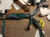
In this photo the outer protective wrap of the OEM wire harness has been removed.
The Fuel Cut-Out Relay connector is in the upper LH corner of the photo, unfortunately the tag has flipped over, and towards the lower RH corner of the photo is the Yellow multi-point connector.
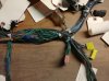
Here is a better photo of the Fuel Cut-Off Relay connector.
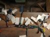
In this photo some of the Black/White conductors can be seen running along the lower portion of the main Wire Harness, with the Yellow multi-point connector on the RH side of the photo.
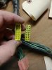
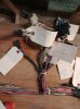
Here is a closer look of the Yellow multi-point connector, it's actually the cap that makes this connector 'multi-point' as all the prongs in the cap are electrically one and the same.
I've distilled one of your earlier posts where you detail the voltage readings on the Black/White conductors to the Fuel Cut-Off Relay.
There are two Black/White conductors going to the Fuel Cut-Off Relay, with the ECM connected, and the Ignition Switch in the ON position, one conductor (let's call this Conductor A) is reading +12vdc to Chassis Ground, the other conductor (let's call this Conductor B) is reading +0.4vdc to Chassis Ground (Note: When the EMC is disconnected, Conductor B will show +12vdc to Chassis Ground.
Additionally, with the EMC disconnected and Conductor B (showing +12vdc), when connected to a load the voltage on Conductor B again drops to 0.4vdc.
I think when voltage drops as you've indicated it's a pretty good bet that the conductor's ability to pass current has been compromised. When no load is present, or a light load such as the voltmeter, the conductor can pass the low current at 12vdc, however when a more substantial load is presented such as the ECM or the Fuel Pump, the conductor can no longer pass the higher current at 12vdc, or at any voltage. The usual culprits for compromised conductors are corrosion at the connections, abraded insulation allowing the conductor to short..., or a break in the conductor.
While it's possible for the conductor to suffer a failure anywhere along it's length, my opinion is that barring physical damage to the conductor at some point, the most likely areas for failure is at or near the ends. After viewing the '05 Wire Harness I think the Yellow multi-point connector is well protected, as are the conductors in the main trunk of the Wire Harness. The four Fuel Cut-Off Relay conductors exiting the main trunk of the Wire Harness are wrapped with a plastic film for protection, I think I would concentrate my powers of examination in this area looking for any signs of abrasion, feeling the conductors for a weak area (indicating possible broken internal wire strands), remove the plastic wrap as necessary to aid in your examination.
I'm surprised that Honda decided to run a dozen conductors from various locations to one central point for connection, and then burying that connection within the Wire Harness.
Seems like a lot of duplicate runs that could have been handled by a single run of one conductor with individual 'branch' connections at the various locations.