To view this article, click on the link to the attached PDF file.
Rostra cruise control installation by altexst1300.
To view this article, click on the link to the attached PDF file.
Rostra cruise control installation by altexst1300.
Last edited by Mellow; 03-25-2007 at 02:11 PM.
Thanks for the info I ordered the divider yesterday. Why are you cutting off the capacitor and how did you know to cut it out? Nice idea with the gold wing switch Ive always used the dashmount switch and find a suitable location for mounting
I finished the installation of the Rostra cruise control using the Gold Wing backlit control. A big thanks to altest1300 for his great instructions. He used the non-backlit control in his instructions. With the backlit control, some of the wire colors have changed from Al’s instructions.
Here are the updated wire colors and parts:
Gold Wing backlit control #35130-MCA-A21 from a 2005 Gold Wing. $137.85 from Hondaparts online.
Hook up 12V with a 4 amp fuse to the Black w/Yellow wire on the Gold Wing switch.
The Black w/Green wire hooks up to the Rostra Red/Brown wire.
The White w/Yellow wire hooks up to the Dark Green Rostra wire.
The White w/Blue wire hooks up to the Yellow Rostra Wire.
The Brown Rostra wire needs to be hooked up to a 10 amp switched circuit. I used a relay that is turned on by power from the Quartet Harness.
In the dipswitch settings, Al’s instructions state that switch 12 is in the “ON” position. The backlit switch is an open circuit switch, so number 12 needs to be in the OFF position.
The Rostra Blue Tach wire gets hooked up to the Blue w/Yellow coil wire. I just made a pig tale so I did not have to cut the coil wire.
To get the backlights to work, I ran switch power from the Quartet harness and hooked it up to the Light Green w/Black wire. This wire also had red squares on it. The solid dark green wire needs to be grounded. Now the backlights will work when the key is on.
If you want to use the Reverse Shift Switch to turn on and off Aux lights, you will use the Yellow w/White and Brown w/Green squares. I ran keyed power from the Quartet Harness to the Yellow/white and hooked the Brown wire to my Moto light relay.
If you have any LED’s for brake lights, you will need to put a relay in to get a good ground for the Rostra Violet wire. Wires to hook up to the relay: #85 to brake negative (+12v when brake is pressed), #86 to ground, #87 not used, 87A Rostra violet wire, #30 to ground.
Below is a photo of what the Gold Wing switch looks like with the lights on.
Dan
![]()
04 ST 1300 1988 NX 650 1988 GL 1500 Gold Wing
STOC 5926 AMA Life
An update. January, 2009
I just purchased a Centrodyne Y060 pulse divider and, found the circuit board is arranged slightly different than the one pictured in altexst1300's original article instructions.
Altexst1300 just PM'd me and, the correct capacitor to clip on the newer board is still the C8. It is the blue one. See new image below.
If you receive an older board like the one pictured in the article, the correct capacitor to clip is the C8. The arrow in the original article illustration is slightly off and, appears to be pointing towards C2.
Last edited by MileHigh; 01-31-2009 at 04:25 PM. Reason: Re-arranged picture album
Mark STOC #6674
In these instructions, under order of installation, you request that we install a "Turbo City fuel pressure regulator" (Optional). I take it that you mean to say that this would be the time to install this device because you have everything apart. Is this a regular part that ST owners install? Does the Rostra cruise work better with this vs. the stock one? Probably a dumb question, I just wonder why you have it in there.
I will be installing my cruise in about 2 months time. Thanks for this great guide. Well done.
You are right, This is a good time to put one in if you want to with the air box out. The FPR got rid of the flat spot I had at around 4000 RPM.
Dan
![]()
04 ST 1300 1988 NX 650 1988 GL 1500 Gold Wing
STOC 5926 AMA Life
Man,,, I would buy Moonburgers and beverages of your choice if I could get this set up on my ST...
I get sweaty palms just thinking about that!!!
I know I am not in any way,,, shape or form able to tackle this set up...
Note: I'd sure like to hear Altexst1300 speak-up sometime. This project is his "baby" after all
. In the meantime, I'll try to offer some thoughts ..
Yes, a lot of folks install the TT FPR, whether they're installing a CC or not. I don't believe it makes the CC work better, but makes the engine feel smoother in the 3-4K RPM range. So I guess it makes the rider feel better. I think you'll like the results of both the FPR and the Rostra CC. Another suggestion in the installation guide is to synchronize the starter valves. I did this as well, using a Carbtune II, and I'm pretty sure it runs cooler now. One nice thing about this CC, is that it isn't affected (effected?) by long ascending hills, or high elevations.
I understand your concerns ACL! In the middle of this thing, I had many occasions where sweaty palms were the norm. I would ask myself, "What have I gotten myself into?", and "Will it ever run again?"![]()
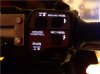
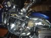
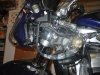
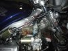
Needless to say, there are quite a few wires involved in this project.. For example, here are a couple pics showing a little progress (note: I varied some from the instructions.. most of my electrical connections to the Rostra are on the left side of the bike, whereas the instructions make the connections on the right side - I didn't think there was enough room on the right because of the ABS modulator. I don't know if Altexst1300's bike has ABS or not).
It takes quite a bit of planning, but the results are well worth the effort!!
Last edited by st13fundred; 01-26-2009 at 12:19 PM.
st13fundred
'04 ST13
There are three kinds of people.. those that can count, and those that can't![]()
If you where closer Terry, I would take you up on your offer.
This was quite a project. The wiring took about a day and, perfecting the linkage took about another day. Just creating a wiring diagram took about half a day.
I did my N/O, back-lit GW switch wiring, like snowmoer and, made my connections on the left side of the bike like st13fundred. I used Hitachi connectors on the left side of the bike. I reversed the aluminum bracket on the throttle cables because the first time, the bracket wanted to slip out. I had to install a clamp to hold the breather hose out of the way of the Futoba arm on the linkage. It was catching at WOT.
I have not had a chance to road test yet as there is snow on the ground. My electrical diagnostics have passed, just waiting for a clear day to road test.
![]()
Last edited by MileHigh; 02-08-2009 at 10:21 AM. Reason: Added image and, corrected credits to snowmoer & st13fundred
Mark STOC #6674
One other modification/change I made was throttle cables.
I have an MCL riser. With the addition of the GoldWing switch, I found the throttle cables tight. On a left lock, WOT, throttle return was slow/binding. I replaced my throttle cables with a "P" model set of throttle cables.
They are about 1-1&1/2" longer. Binding on WOT, left lock, is completely gone!
PN#'s
17910-MCS-A30, throttle cable A
17920-MCS-A30, throttle cable B
Picture of difference is attached. Original cables are on the bottom.
![]()
Mark STOC #6674