Blinking Fuel Gauge-Troubleshooting

v8-7

Site Supporter
Joined
Jul 13, 2010
Messages
1,188
Location
Bradenton, Fl
I'm not sure of the circuit theory, but I think the thermistor functions as a switch to tell the computer to start the "miles remaining " countdown.

If you have more insight as to the circuit operation , post it up !

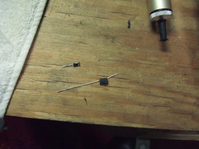
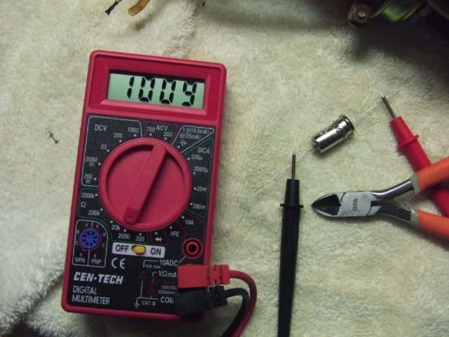
I ordered some thermistors from Mouser as the gauge has been working intermittently.

The part I used is the wrong form factor as it should have coaxial leads , but it works fine.

Do not cut the leads until the end .

To be safe , I put some shrink tubing around the thermistor to keep it from touching the can .


My gauge has been working since doing this 3 days ago, but because it was intermittent,
I'm not yet confident my problem is fixed , but if it was the thermistor, this should do it .


To do this job:

You will be working around gasoline , Don't be stupid or blame me if you blow up stuff.

special tools : 8 mm hex bit , soldering gun , solder , solder sucker or braid .

The fuel level should be below the upper tank .
I drove ~250 miles after filing up the tank and the level was well below the upper tank.

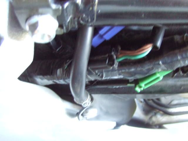
Disconnect the negative lead from the battery .

Remove the seat and the left and right side side covers .

Remove the seat bracket .

Remove the fuel pump assembly.


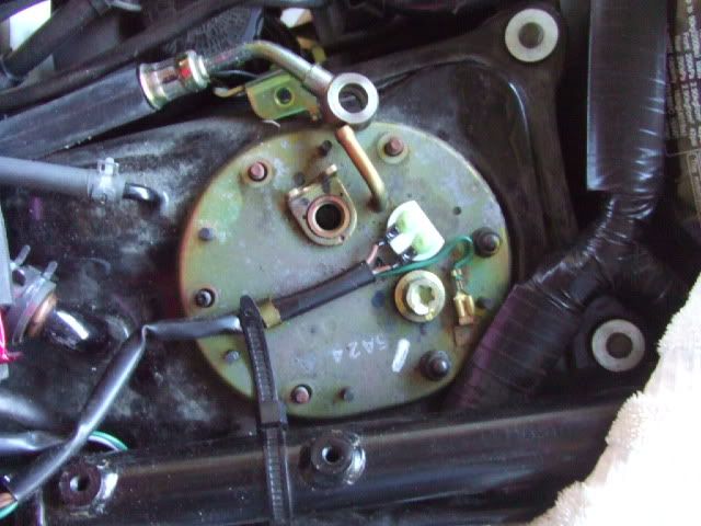
Drain the fuel out of the pump and filter.

Remove the bracket that holds the thermistor can .


Cut the wire off the can close to the can .

De-solder the can from the bracket


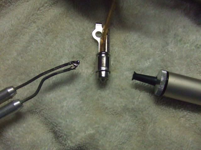
Slice the can open .


Unsolder the bottom of the thermistor to separate the two halves of the can .

There is a hole in the bottom of the can that will be opened up when you unsolder the wire.

Pull or cut the wire at the top ( inside ) of the can . remove the thermistor .

There will now be a hole at the top of the can as well as the bottom.

Insert the new thermistor leads into the can top and bottom .


Clamp the can back together and solder it around the circumference.


The can is not "sealed You will note that there are 3 holes and the top and bottom that are open to the fuel, so an airtight seal when soldering the can back together is not required .

Now center the thermistor inside the can, by pulling the leads.

Solder the top and bottom of the leads to the can .

Solder the wire from the bike connector to the lead .


Reinsert the can into the bracket . I had to slightly enlarge the bracket hole to allow
for the new solder joint around the can circumference .


Tack solder the can back to the bracket .

Re-assemble , check for fuel leaks .

More pictures are here :

http://s219.photobucket.com/albums/cc215/v8-7/fuel gauge/


Edit : part that has worked 2 times in a row is digikey 570-1089-nd
http://search.digikey.com/scripts/DkSearch/dksus.dll?lang=en&site=US&WT.z_homepage_link=hp_go_button&KeyWords=570-1089-nd&x=0&y=0
 
Last edited:
Joined
Nov 16, 2010
Messages
2
Location
Cape Town, South Africa
Has anyone actually successfully done the operation below on a ST1300A? I would like to know because my ST developed this problem on Saturday morning and I plan to implement this solution if it has been successfully on an ST.

I found this info while googling around.
Although it is for a Gold Wing warning light, I bet it's the same thermistor .

If my gauge stops working again, I'll probably pull the pump unit out and try to replace the thermistor .

"With that said, and many thanks to the unknown author for the detail presented, here is the best documentation on replacing the Low Fuel Level sensor that I have seen.

GL-1500 Fuel Reserve Sensor Repair:

Many sensors just stop working, so there's NO low fuel light warning.

This is how I accomplished my repair in about 45 minutes, was very easy to do; costs almost nothing, compared to Honda's fix: Buying new fuel pump assembly, at cost of $300+.

This is written for that percentage of the population who might not be as mechanically proficient as you; please take no offense. You'll need to purchase a thermistor from a local electronic parts supply house, with the following specs: 1000 ohms @ 25 degrees C, NTC (Negative Temp. Co-efficient).

To begin with: you'll be working around an open fuel tank. If you don't understand spark, static electricity, volatile vapors, 3rd degree burns, death; your house, garage, Wing burning & any other potential risk of working around gasoline/ vapors, I strongly recommend you pay the price and have a Honda shop do the work. You must be willing to take full responsibility for whatever may happen. This is very dangerous; do it outside. Also, if you aren't proficient at soldering, find a friend who is.

With all that understood, remove the seat.

There are (six) 10mm nuts on the top of the fuel pump assembly, remove them after you disconnect the electrical leads. As you disconnect the fuel line, have a rag handy to catch fuel that will run out of the hose. Trust me; you'll need to do this. Get another rag handy for the following step.

With everything disconnected, slowly lift fuel pump assembly. You'll notice another fuel line connected INSIDE the tank. Slide it off and work fuel pump assembly out of opening. Wipe off excess gas, then put a rag over open hole to minimize/ contain vapors. Let unit dry in the sun a few minutes. The fuel reserve sensor is what's best described as a "can" halfway down mounting arm of the fuel pump. It has one lead soldered to it. Pry, wiggle, push or otherwise GENTLY work the can free of it's mount on arm.

Don't bother to unscrew mount from the arm; just get the can out without ruining it. You'll need to bend the tabs to get it free; that's OK. Unsolder the single lead on can. Don't cut it; unsolder it.

Now you're holding the can only, in your hand. There's a base lip on the can, at the lead end. Slice the can open all the way around that lip, I used a Dremel tool and it worked easily.

Looking at other end of the can, you'll see a solder blob. That's where the other lead is attached to the can. Unsolder that and remove the larger end of the can; set it aside.

Unsolder the other end of thermistor and remove it completely from the can unit. Take new thermistor, cut ONE LEAD to a length of about 1/2" max. Leave the other lead full length. Solder short lead to the base (disc) center conductor area, where you just removed faulty sensor; make a good connection.

When putting the can together, route the other lead out end of the can, through hole. Be very careful when bending leads. You should hold them with needle nose pliers as a strain relief. Push can together, solder lead in place. You may also solder can itself shut. Do this only for some rigidity; don't try to seal it all the way around with solder.

Solder the single wire back on to sensor and place can back in its’ mount on pump arm. You'll need to squeeze mount to pinch the can. I tack-soldered mine back in it's mount; it held nicely. Put it all back together; it'll work fine."


( part # 527-2004-1K. DIA .22 1k Ohm. Cost was $1.07 each. It was available from http://www.mouser.com )[/QUOTE]
 

v8-7

Site Supporter
Joined
Jul 13, 2010
Messages
1,188
Location
Bradenton, Fl
Unfortunately that thermistor doesn't work,

I used it and went from always blinking - to it works ok until 2 bars and then just stays there and never starts the count-down.

I've now tried 3 different thermistors and have a 4th one on the way .

I'm down to doing this job in 45 minutes or less now ...:^)

Honda will not give out out the therm specs, claiming it's a trade secret .
 
Joined
Nov 16, 2010
Messages
2
Location
Cape Town, South Africa
Thanks "V8-7"! That is very useful feedback. Any electronic wizards out there who can reverse engineer that thermistor on a unit that is in perfect working order? Is that a legal question? Oh yes, how about ... if many of us go the "trial-and-error route" and post our "Thermistors-that-didn't-work" on a list, we (ST-Owners) will eventually crack it!! :wasntme
 

v8-7

Site Supporter
Joined
Jul 13, 2010
Messages
1,188
Location
Bradenton, Fl
Finally , it looks like I have a working fuel gauge.

Looks like #4 is working .

I have gone through 2 full tanks of fuel and both times, the gauge went to 1 bar flashing and started the remaining miles countdown.

That's not to say it is the best part , only that it seems to be at least close enough to work properly .


The resistance goes down in relation to the current flowing through the thermistor. However, ambient air temp may play a small role.

My testing went down to outside temps of ~ 67f. If it is any colder, perhaps even 66 f , this part may not work . Since I'm in Florida,
I probably won't be riding in cooler air for at least 7-8 months .

The part # is digikey 570-1089-ND.

http://search.digikey.com/scripts/DkSearch/dksus.dll?lang=en&site=US&WT.z_homepage_link=hp_go_button&KeyWords=570-1089-nd&x=0&y=0

Since there was a good price break @ 10 units, and I was going to buy 3 anyway, I bought 10.

If you're having this problem, and you intend to attempt this fix it yourself, lmk and I can send you a part .

Stan
 
Joined
Dec 17, 2004
Messages
20
Location
Woodland, CA
v8-7: (started out as a PM, but I should share.)

Any update on part #4 with respect to temperatures?

I've been staring at my blinking gauge for too long now -- and badly missing my MPG display -- so I thought it's time to try it. So if you don't mind a couple quick questions:

-- Any problems with the lower tank/pump gasket in those multiple tries? Should I have one on-hand before I attempt this?

-- Did that fourth thermistor do the trick for lower temperatures too? I live in SF Bay Area which does see freezing temps a few times over the winters, although I ride year-round.


-- An optional question - any guess on the optimal break/make resistance the gauge cluster is looking for? I was thinking about pulling out a connector pin and rigging up a pot to ground to test whether something other than the thermistor is the culprit. From your posts, it seems that perhaps a 5K should be plenty of range to test this. Anyone tried it?
 

v8-7

Site Supporter
Joined
Jul 13, 2010
Messages
1,188
Location
Bradenton, Fl
Fist off.. This is your bike, your reality and your life .

I'm not responsible if you blow up your own bike and/or yourself .

You are taking advice from "just some guy" on the internet.

I am not an engineer and did not even stay at a Holiday Inn last night.


-- Any problems with the lower tank/pump gasket in those multiple tries? Should I have one on-hand before I attempt this?

The manual calls for a new gasket.. I reused mine .
Be careful, it can leak gas at that point, in fact ~ 5 gallons of it if you fill up the tank.

The flange mating surface on the lower tank that mates to the fuel pump is
very thin and easily bends .

The way the fuel pump mounts to it is off balance so it's surprisingly easy to pinch the wires between the lower tank and the fuel pump .


-- Did that fourth thermistor do the trick for lower temperatures too? I live in SF Bay Area which does see freezing temps a few times over the winters, although I ride year-round.


I've ridden at around 40 degrees and it was fine.


-- An optional question - any guess on the optimal break/make resistance the gauge cluster is looking for? I was thinking about pulling out a connector pin and rigging up a pot to ground to test whether something other than the thermistor is the culprit. From your posts, it seems that perhaps a 5K should be plenty of range to test this. Anyone tried it?[/quote]


The open resistance is around 1.5k ohm.

The specs for the thermistor I used should be on digikeys' sight .

Probably close to 0 ohms, but I don't know of I would short it out as it may cause bigger problems.

Looks like at 60 centigrade, the resistance drops down to .2 ohms

There is also a 20 second time delay built into the thermisitor.

I still have a few thermisitors left . Pm me if you want one.
 
Last edited:
Joined
Dec 17, 2004
Messages
20
Location
Woodland, CA
... I'm not responsible if you blow up your own bike and/or yourself ...
Of course! I am the master of my own fate. I'm also a technoweenie that can't stand to not get my fingers into the work, so it's all good.

Anyhow...

I still have a few thermisitors left . Pm me if you want one.
Thanks for the offer, I may take you up on it. I want to do a little more debugging, first. When this problem occurred originally, I ran through the steps in the service manual, and according to all the readings I got and the troubleshooting results in the manual, it says I need either a new pump assembly or a gauge cluster, neither which are trivial investments.

So my first intent is to trouble-shoot further. I'm a little unclear on the operating dynamics of a thermistor, so I'm doing some research. (I'm an electronics hobbyist and have a few good test tools to work with.)

What I'd really love to find is someone's discarded pump assembly in which the pump failed and not the thermistor, so I could analyze that known-good thermistor's characteristics. (Or, of course, to just take the thermistor off the assembly...!)

Thanks for sharing your info!
 
Joined
Apr 25, 2007
Messages
4,950
Age
62
Location
New Jersey
Bike
st1300 '04
STOC #
7163
Thermisters change resistance in response to temperature change.
Being a resistor they also self heat in response to a current.
So...
When they are not submerged in gasoline they are free to self heat.

TMI
LINK
 
Last edited:
Joined
Dec 17, 2004
Messages
20
Location
Woodland, CA
Thermisters change resistance in response to temperature change.
Being a resistor they also self heat in response to a current.
So...
When they are not submerged in gasoline they are free to self heat.

TMI
LINK
I was wondering about that; I'd be curious to know how much it would self-heat while dry. I'll have a good look at that datasheet!

Thanks!
 

Blrfl

Natural Rider Enhancement
Joined
Aug 24, 2005
Messages
5,601
Age
55
Location
Northern Virginia
Bike
Fast Blue One
STOC #
4837
Probably very little. In most threshold applications they run it in series with another resistor, which keeps the amount of current flowing through it down to almost nothing.

Given the amount of heat that's already down there, I doubt anything the thermistor dissipates would amount to ... ohboyohboyohboy, I get to say this one again ... a fart in a windstorm.

--Mark
 
Joined
Dec 17, 2004
Messages
20
Location
Woodland, CA
Probably very little. In most threshold applications they run it in series with another resistor, which keeps the amount of current flowing through it down to almost nothing.

Given the amount of heat that's already down there, I doubt anything the thermistor dissipates would amount to ... ohboyohboyohboy, I get to say this one again ... a fart in a windstorm.

--Mark
That's the thing, though - the difference would need to be great enough, or the threshold stable enough, so that the controller has a solid chance of interpreting the results correctly. Perhaps the controller saves some threshold value based on the upper tank sender showing fuel in the upper tank, so that when the lower tank does empty enough to expose the thermistor, the controller will be able to compare the value with the upper-tank-sufficiently-full value -- and thus, the thermistor's characteristics are less important.

I guess there's nothing else to do but try it out.

Again, I think my first attempt should be to bypass the thermistor with a 5 or 10k pot and see if the blinking gauge at least goes back to showing the upper tank. The wiring loom in there is pretty tight though, as I recall, might be a challenge to get a pin out of the connector.
 
Joined
Nov 23, 2018
Messages
9
Age
45
Location
Miami, FL
Hi there, I realize this thread is quite old, but I'm wondering if the thermistor v8-7 mentioned is the only option for this fix? It looks like Digikey will only sell them in boxes of 500 now. I've been living with an annoying blinking fuel gauge for 8 years and have decided it's time to fix it. Thanks!
 

fnmag

R.I.P. - 2020
Rest In Peace
Joined
Mar 21, 2009
Messages
1,417
Location
Desert Southwest
Bike
'06 ST1300/Burgmn400
Hi there, I realize this thread is quite old, but I'm wondering if the thermistor v8-7 mentioned is the only option for this fix? It looks like Digikey will only sell them in boxes of 500 now. I've been living with an annoying blinking fuel gauge for 8 years and have decided it's time to fix it. Thanks!
Welcome to the forum.
Hope you sort out your blinking fuel gauge light.
 
Joined
Nov 23, 2018
Messages
9
Age
45
Location
Miami, FL
Just as a follow-up, I can confirm that the following thermistor from Mouser works:
Mouser Part number: 527-2004-1K
Mfr. #: RL2004-582-97-D1
Desc.: NTC Thermistors DIA .22 1k Ohm


Thanks v8-7 for the very helpful write up. Nice to have a working fuel gauge after 8 years!
 

v8-7

Site Supporter
Joined
Jul 13, 2010
Messages
1,188
Location
Bradenton, Fl
Good find on the new part # and thanks for posting it.
I bought 10 of the items , gave a few out but the remaining spares I have, have found a good hiding place since I moved 2 1/2 years ago..
 
Top Bottom