
Starting Issues
- Thread starter Trapperdog
- Start date

The bank angle sensor cut's off the spark and the fuel pump but still allows the engine to turn over when it's tripped correct? You have no spark and no power to fuel pump and no FI light. Did you verify the sensor activates the relay when you tilt it? I would check all wires and connections from the ECM to the sensor. On my BMW r1100 I had the insulation on the wires to my crank position indicator decay and the bike would die during heavy rain. You might want to check the wires and indicator if you haven't already.
OP
OP
Thanks, yes I had previously tested conduductiity on the wires but did just pop the nose off the bike and removed the BAS. I did tilt it with the ignition and run switch on while holding the relay and the relay did click. I did not perform tests on the relay conductors during this test though.The bank angle sensor cut's off the spark and the fuel pump but still allows the engine to turn over when it's tripped correct? You have no spark and no power to fuel pump and no FI light. Did you verify the sensor activates the relay when you tilt it? I would check all wires and connections from the ECM to the sensor. On my BMW r1100 I had the insulation on the wires to my crank position indicator decay and the bike would die during heavy rain. You might want to check the wires and indicator if you haven't already.
One of my initial thoughts was also the CKP sensor but I haven't gone through any tests on that. Oddly, my service schematic shoes two CKP sensors, not sure what that's about.
Last edited:
There is a crankshaft position sensor and also a camshaft position sensor (not sure why?) They both share a common wire going to the ECM.
Last edited:
OP
OP
I believe they listed the CMP as a CKP thereby showing two CKP's.
- Joined
- Mar 18, 2006
- Messages
- 2,829
- Age
- 70
- Location
- Ilkley, W Yorkshire, UK
- Bike
- 2013 ST1300 A9
- 2024 Miles
- 000679
- STOC #
- 2570
Hi again. Sorry - I have been enjoying myself on a 2000 mile tour, but took a little time out to send a PM at some point. Good to see David is also on the case !
It could also be the faulty power supply from the fuse.
It could also be the relay itself.
From previous posts and diagnostic tests, it seems the fault is narrowed to the Bl/Wh power supply which is turned on by the Fuel Cut Off relay and which seems to provide power for a whole host of components.
It could be one, two or all 3 of these things. To find where the fault is, you first need to be certain what the fault is.
The power from the fuse. I put a link in Post #22 which hinted that a corroded wire could show correct voltage, but that didn't mean that it could supply the required amount of current.
The relay.
We know that the Bl/Wh lead from the Bank Angle Sensor Relay to the fuel cut off relay is not providing the power required, but the other Bl/Wh connector at the same relay is providing power. (You bridged it to the brown wire to get the pump motor to spring into life. )
So - have you tried connecting these two together to see if the problem goes away ? If the fault is in that single Bl/Wh lead from the bank angle sensor to the fuel cut off relay, this should work. The two leads are connected together elsewhere in the harness, and we know that the other Bl/wh terminal provides enough power to make the fuel pump work. (You might want to get a second opinion - eg from Anna'sDad - before doing this.)
You might need to make up a small harness with 4 short wires each with a male and female spade connector in order to do this - unless you can push a couple of probes in from the rear in order to connect the two terminals. Make sure that nothing touches earth or the terminal for the green wire when doing this.
----------------
I'm ignoring the voltage drop for the time being - we don't know what is going on with the rest of the circuit, particularly inside the ECM to which one end of the Bl/Wh cables are connected. (I'm thinking here about the behaviour of the readings of the Bank Angle sensor. The manual says to check it should show 0-1volts on the red/orange wire, yet this is the route to earth for the 12v power from the Run/Stop switch that allows the bank angle sensor relay to be activated. Normal electrical logic suggests that this should not produce a reading at all. But as with the ECM, we don't know what is going on in the electronics in the sensor.)
-------------
David's comment that the Black white leads have many connections in the main harness is a brilliant one. I'm looking at the schematic, and it all looks clear as to where the bl/wh leads are connected. But in making the schematic easier to read, Honda have hidden the actual routes of the cables.
I would be tempted to measure the resistance of the wire from the Bl/Wh lead at the fuel cut off relay (the one that you know works) to each of the others in David's simplified diagram. See what crops up. They should all be quite small , but we know that the resistance between the two Bl/Wh connectors at the fuel cut off relay will be higher as that lead doesn't work. It might help to identify if any of the other leads have developed a problem.
It could also be the faulty power supply from the fuse.
It could also be the relay itself.
From previous posts and diagnostic tests, it seems the fault is narrowed to the Bl/Wh power supply which is turned on by the Fuel Cut Off relay and which seems to provide power for a whole host of components.
It could be one, two or all 3 of these things. To find where the fault is, you first need to be certain what the fault is.
The power from the fuse. I put a link in Post #22 which hinted that a corroded wire could show correct voltage, but that didn't mean that it could supply the required amount of current.
However, you have bridged the power to the brown fuel cut off relay and established the fuel pump whines.
The relay.
You have switched out the relay with a windscreen relay and it didn't fix the fault. That doesn't mean that the original relay was OK - it just means that there is a fault elsewhere - possibly as well as a relay fault. We know the relay clicks, so we know that the Fuel Cut off relay is getting power to its coil and has a workable earth connection. We don't know that the 'switch' is actually working.
So we can assume that the brown wire is OK to the fuel pump (from a previous test); we can assume that the bl/wh lead to the relay coil is ok; we can say that the green earth wire is ok.
So we can assume that the brown wire is OK to the fuel pump (from a previous test); we can assume that the bl/wh lead to the relay coil is ok; we can say that the green earth wire is ok.
We know that the Bl/Wh lead from the Bank Angle Sensor Relay to the fuel cut off relay is not providing the power required, but the other Bl/Wh connector at the same relay is providing power. (You bridged it to the brown wire to get the pump motor to spring into life. )
So - have you tried connecting these two together to see if the problem goes away ? If the fault is in that single Bl/Wh lead from the bank angle sensor to the fuel cut off relay, this should work. The two leads are connected together elsewhere in the harness, and we know that the other Bl/wh terminal provides enough power to make the fuel pump work. (You might want to get a second opinion - eg from Anna'sDad - before doing this.)
You might need to make up a small harness with 4 short wires each with a male and female spade connector in order to do this - unless you can push a couple of probes in from the rear in order to connect the two terminals. Make sure that nothing touches earth or the terminal for the green wire when doing this.
----------------
I'm ignoring the voltage drop for the time being - we don't know what is going on with the rest of the circuit, particularly inside the ECM to which one end of the Bl/Wh cables are connected. (I'm thinking here about the behaviour of the readings of the Bank Angle sensor. The manual says to check it should show 0-1volts on the red/orange wire, yet this is the route to earth for the 12v power from the Run/Stop switch that allows the bank angle sensor relay to be activated. Normal electrical logic suggests that this should not produce a reading at all. But as with the ECM, we don't know what is going on in the electronics in the sensor.)
-------------
David's comment that the Black white leads have many connections in the main harness is a brilliant one. I'm looking at the schematic, and it all looks clear as to where the bl/wh leads are connected. But in making the schematic easier to read, Honda have hidden the actual routes of the cables.
I would be tempted to measure the resistance of the wire from the Bl/Wh lead at the fuel cut off relay (the one that you know works) to each of the others in David's simplified diagram. See what crops up. They should all be quite small , but we know that the resistance between the two Bl/Wh connectors at the fuel cut off relay will be higher as that lead doesn't work. It might help to identify if any of the other leads have developed a problem.
Can you expand on this?I do have some main harness wear from the frame that I have investigated previously, but will do so more in depth.
Depending on where along the wiring harness the wear is occurring, we might be able to make an educated guess relating the wear location on the harness, with the individual low voltage conductors.
Do you have a photo of the worn portion of the wiring harness?
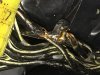
I think I can answer this for Roger, its on the main bundle where it crosses under the riders seat area and directs down under the frame tube.
This is the area where the wire harness has "flat supports" under the tape to protect the wires. We found the tape worn/torn open, but so far no visible damage to the wires.
Hopefully Roger can post a picture.
Again....thank you all for helping him with this very frustrating trouble shooting electrical issue.
Igofar
OP
OP
thanks, RogerHi again. Sorry - I have been enjoying myself on a 2000 mile tour, but took a little time out to send a PM at some point. Good to see David is also on the case !
Hope you're having a fantastic time, thanks for checking in!
It could be one, two or all 3 of these things. To find where the fault is, you first need to be certain what the fault is.
The power from the fuse. I put a link in Post #22 which hinted that a corroded wire could show correct voltage, but that didn't mean that it could supply the required amount of current.
However, you have bridged the power to the brown fuel cut off relay and established the fuel pump whines.
The relay.
You have switched out the relay with a windscreen relay and it didn't fix the fault. That doesn't mean that the original relay was OK - it just means that there is a fault elsewhere - possibly as well as a relay fault. We know the relay clicks, so we know that the Fuel Cut off relay is getting power to its coil and has a workable earth connection. We don't know that the 'switch' is actually working.
So we can assume that the brown wire is OK to the fuel pump (from a previous test); we can assume that the bl/wh lead to the relay coil is ok; we can say that the green earth wire is ok.
We know that the Bl/Wh lead from the Bank Angle Sensor Relay to the fuel cut off relay is not providing the power required, but the other Bl/Wh connector at the same relay is providing power. (You bridged it to the brown wire to get the pump motor to spring into life. )
So - have you tried connecting these two together to see if the problem goes away ? If the fault is in that single Bl/Wh lead from the bank angle sensor to the fuel cut off relay, this should work. The two leads are connected together elsewhere in the harness, and we know that the other Bl/wh terminal provides enough power to make the fuel pump work. (You might want to get a second opinion - eg from Anna'sDad - before doing this.)
Ill try piggy backing from the rear of the connector.
----------------
I'm ignoring the voltage drop for the time being - we don't know what is going on with the rest of the circuit, particularly inside the ECM to which one end of the Bl/Wh cables are connected. (I'm thinking here about the behaviour of the readings of the Bank Angle sensor. The manual says to check it should show 0-1volts on the red/orange wire, yet this is the route to earth for the 12v power from the Run/Stop switch that allows the bank angle sensor relay to be activated. Normal electrical logic suggests that this should not produce a reading at all. But as with the ECM, we don't know what is going on in the electronics in the sensor.)
The B/W conductors at the two coils and the data/service connector all exhibit the same behavior as the B/W fuel pump trigger conductor at the BAS relay. With the ECM unplugged, they all show 12.x Volts. If a load (incandescent test light) is bridged between one and ground, it does not illuminate though. If the ECM is plugged in, they all read .4xx Volts. It should be noted that the R/O conductor from the BAS to the BAS relay does indeed show .5 Volts, however when the BAS is activated (tilted) the R/O conductor reads at 12.x Volts and the relay clicks. At that point, all the B/W conductors read at 0 Volts instead of the previous .4xx Volts
-------------
David's comment that the Black white leads have many connections in the main harness is a brilliant one. I'm looking at the schematic, and it all looks clear as to where the bl/wh leads are connected. But in making the schematic easier to read, Honda have hidden the actual routes of the cables.
I would be tempted to measure the resistance of the wire from the Bl/Wh lead at the fuel cut off relay (the one that you know works) to each of the others in David's simplified diagram. See what crops up. They should all be quite small , but we know that the resistance between the two Bl/Wh connectors at the fuel cut off relay will be higher as that lead doesn't work. It might help to identify if any of the other leads have developed a problem
Will do
.
OP
OP
Thanks, I see Larry responded but I'll try and get a pic. It looked large but minimal as the tape covering was gone but the integrity of the individual conductors looked good. I'll be pulling the lower tank (hopefully) to get a better look as well as checking out the yellow and pink joint connectors in front of the tank. The tank is empty now and ready to pull minus removal of the fuel rail hose, but it sure looks like a tight fit with the main harness crossing over the left rear corner of the tank. Should be interesting.Can you expand on this?
Depending on where along the wiring harness the wear is occurring, we might be able to make an educated guess relating the wear location on the harness, with the individual low voltage conductors.
Do you have a photo of the worn portion of the wiring harness?
Thanks, Roger
OP
OP
Well I tried to remove the lower tank but soon realized the beast was not going to relinquish it with the harness in the way so I decided to read the directions (service manual). It states that the seat rail, battery, rear fender and tire need to be removed. So reverting to plan "b", I'll see about accessing the yellow and pink joint connectors from above, at least enough to determine what state they are in. If repairs are needed there then either the lower tank or throttle bodies will need to be removed. Meanwhile I'll give a go at the electrical tests previously mentioned
OP
OP
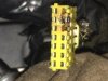
Well I believe I've found the problem, if not the problem, a problem. It seems that the yellow B/W joint connector under the tank was previously compromised and a well intending mechanic rectified the problem by globbing a huge amount of solder and combining the problematic conductor to a good conductor. Now it looks like the good conductor has fried in the joint connector due to too much current passing through it.
My thoughts for repair would be to purchase a used harness, cut off the joint connector leaving enough of the individual conductors to solder each conductor to my existing harness (having cut off my yellow joint connector). However, I'm completely open to suggestions as this involves some tedious work in a cramped space
My thoughts for repair would be to purchase a used harness, cut off the joint connector leaving enough of the individual conductors to solder each conductor to my existing harness (having cut off my yellow joint connector). However, I'm completely open to suggestions as this involves some tedious work in a cramped space
Attachments
-
 161.5 KB Views: 43
 -
 173.9 KB Views: 41
Last edited:
How many of the wires are fried? What do the rest of the wires and connections look like? Could you bypass the joint connector with just the fried wires? Atleast to see if it runs.
OP
OP
Although I haven't run tests, I believe one of the two affected conductors is what powers the entire joint connector. I too originally thought as you but either way this issue needs to be addressed. One friend said just solder all the wires together and dip it liquid electrical tape, thought of that but.......How many of the wires are fried? What do the rest of the wires and connections look like? Could you bypass the joint connector with just the fried wires? Atleast to see if it runs.
Thanks
Tom Mac 04a
Site Supporter
wires don't burn like that without a reason... built up resistance for some reason or to much draw .
use a good dielectric paste in there when assem'ing
I would use another connector for the effected wires and bypass
EDIT... if it powers all , then not much choice than a new spliced connector
use a good dielectric paste in there when assem'ing
I would use another connector for the effected wires and bypass
EDIT... if it powers all , then not much choice than a new spliced connector
OP
OP
i can understand why the connector fried this time, the two wires soldered together had double the current passing through the one pin. I'm a bit worried why the cut and soldered conductor fried previously necessitating that repair. I'll be checking the schematic and testing the two affected conductors to find their end point and resistance.wires don't burn like that without a reason... built up resistance for some reason or to much draw .
use a good dielectric paste in there when assem'ing
I would use another connector for the effected wires and bypass
EDIT... if it powers all , then not much choice than a new spliced connector
Two other repair options I thought of were to figure out how to release the good conductor pins from the joint connector, solder additional conductor and add new pins to the two affected conductors and either sourcing a new or used joint connector and reattaching it to the conductor pins.this would minimalize additional cut and soldering of the existing conductors but requires sourcing the connector and more importantly the pins.
Thanks
- Joined
- Nov 20, 2005
- Messages
- 9,520
- Location
- Cedar City, Utah
- Bike
- 12/04 ST 1300s
- 2024 Miles
- 000420
- STOC #
- 5901
Roger, Great you found the issue, but what a PIA!
I would be tempted to replace it all with a good used harness. There might be other hidden issues caused by the fried wires/connector.
I would be tempted to replace it all with a good used harness. There might be other hidden issues caused by the fried wires/connector.
Last edited:
- Joined
- Mar 18, 2006
- Messages
- 2,829
- Age
- 70
- Location
- Ilkley, W Yorkshire, UK
- Bike
- 2013 ST1300 A9
- 2024 Miles
- 000679
- STOC #
- 2570
That is a good find, Roger, and would certainly produce the symptoms that you have been showing us.
I have never seen that yellow 'connector' - so all of the black / white cables go into the connector, and the fitting of the cap connects them all together ?
Not that it makes much difference electrically, but all the black/white cables come together at one point - not because they need to be connected together, but because they all need a power supply. Since the cap isn't on, all of the cables are disconnected from each other. You should be able to quickly work out which was is providing the 12v and whether it is one of the damaged cables or whether it is still intact in the yellow connector. The power, incidentally, comes from the output terminal of the Bank Angle Sensor Relay when the Bank Angle Sensor turns the relay on. The source of the 12v power is via the Black / Pink cable which comes from a 20A fuse in the rearward fuse box.
You could locate a second hand terminal block and then fit the wires into that. The terminals, by the way, can usually be released by pressing down a latch of metal on one side of the terminal itself. It usually requires a tool or a small watchmakers screwdriver. I can provide some photos of terminals that look to be similar if you are unsure about this.
Alternatively, as previously suggested, you could install a new connector into which the damaged wires could be placed. They would need to be fed from the same power supply as the others - ie the output Bl/W cable from the Bank Angle Sensor Relay, and this would need to be have enough wires spliced from it in order to feed each of the newly located damaged wires.
If the 12v supply is one of the damaged wires, then I would fit a new terminal and put it into an undamaged slot in the old yellow connector. Take out one of the others for this, and put the ejected cable into your new connector instead.
Now - you don't know what current these cables are going to be carrying, but you do know that the total current doesn't exceed 20Amps. So the new power feeds have to use 20Amp cable. I find the newer thinwall stuff to be better to work with.
There is no need to connect the new connector to the existing yellow block - everything will be connected via the power supply from the output of the bank angle sensor relay. I am assuming that the yellow cap connects everything together here. I am also assuming that the existing 12v feed from the relay is good.
Finally, you may want to check what might have caused the problem in the first place. It could be corrosion, reducing the conductivity of the cable / terminals and increasing the heat. It could be that someone looking for a convenient 12v supply had been told to tap into any bl/w cable in the harness, and then ran something like an 18amp horn off it ! It might be that a problem of this nature has already been removed.
As mentioned previously by someone. Use dilectric grease on all terminals to protect them. If splicing / joining wires - make sure that they are physically sound. Grease them too and protect them.
---------------
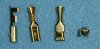
From the photos, those terminals in the yellow block look very much like the terminals used in the Hitachi 2P, 3P, 4P, 6P and 9P connectors. I can send you a quality photo with dimensions - if they are the same, then it should be easy enough to buy new ones.
[Edit]
Here you are - you may be able to tell if these are the correct ones for that yellow block.
16.5 mm long, 4.2mm wide, 2.65mm high (excluding the 'latch')
I have never seen that yellow 'connector' - so all of the black / white cables go into the connector, and the fitting of the cap connects them all together ?
Not that it makes much difference electrically, but all the black/white cables come together at one point - not because they need to be connected together, but because they all need a power supply. Since the cap isn't on, all of the cables are disconnected from each other. You should be able to quickly work out which was is providing the 12v and whether it is one of the damaged cables or whether it is still intact in the yellow connector. The power, incidentally, comes from the output terminal of the Bank Angle Sensor Relay when the Bank Angle Sensor turns the relay on. The source of the 12v power is via the Black / Pink cable which comes from a 20A fuse in the rearward fuse box.
You could locate a second hand terminal block and then fit the wires into that. The terminals, by the way, can usually be released by pressing down a latch of metal on one side of the terminal itself. It usually requires a tool or a small watchmakers screwdriver. I can provide some photos of terminals that look to be similar if you are unsure about this.
Alternatively, as previously suggested, you could install a new connector into which the damaged wires could be placed. They would need to be fed from the same power supply as the others - ie the output Bl/W cable from the Bank Angle Sensor Relay, and this would need to be have enough wires spliced from it in order to feed each of the newly located damaged wires.
If the 12v supply is one of the damaged wires, then I would fit a new terminal and put it into an undamaged slot in the old yellow connector. Take out one of the others for this, and put the ejected cable into your new connector instead.
Now - you don't know what current these cables are going to be carrying, but you do know that the total current doesn't exceed 20Amps. So the new power feeds have to use 20Amp cable. I find the newer thinwall stuff to be better to work with.
There is no need to connect the new connector to the existing yellow block - everything will be connected via the power supply from the output of the bank angle sensor relay. I am assuming that the yellow cap connects everything together here. I am also assuming that the existing 12v feed from the relay is good.
Finally, you may want to check what might have caused the problem in the first place. It could be corrosion, reducing the conductivity of the cable / terminals and increasing the heat. It could be that someone looking for a convenient 12v supply had been told to tap into any bl/w cable in the harness, and then ran something like an 18amp horn off it ! It might be that a problem of this nature has already been removed.
As mentioned previously by someone. Use dilectric grease on all terminals to protect them. If splicing / joining wires - make sure that they are physically sound. Grease them too and protect them.
---------------
From the photos, those terminals in the yellow block look very much like the terminals used in the Hitachi 2P, 3P, 4P, 6P and 9P connectors. I can send you a quality photo with dimensions - if they are the same, then it should be easy enough to buy new ones.
[Edit]
Here you are - you may be able to tell if these are the correct ones for that yellow block.
16.5 mm long, 4.2mm wide, 2.65mm high (excluding the 'latch')
Last edited:
OP
OP
Thanks, it's Roger though, not Peter. You can call me Pete though.Peter, Great you found the issue, but what a PIA!
I would be tempted to replace it all with a good used harness. There might be other hidden issues caused by the fried wires/connector.
") .
. I too would be temped to replace the harness, but it's a lot of work and the police harness looks to be specific. Used police harness have generally been *******ized pretty much as well
- Joined
- Nov 20, 2005
- Messages
- 9,520
- Location
- Cedar City, Utah
- Bike
- 12/04 ST 1300s
- 2024 Miles
- 000420
- STOC #
- 5901
I knew that...had a senior moment!Thanks, it's Roger though, not Peter. You can call me Pete though.
I too would be temped to replace the harness, but it's a lot of work and the police harness looks to be specific. Used police harness have generally been *******ized pretty much as well
I wonder if a good ABS Harness from a non P model would fit/work?