No manual as yet. trying to get to the bottom of no charging issue. To check for alternator voltage output "three yellow wires"----does this refer to small yellows going into regulator?? can unit be run with regulator unplugged?? Had wire issues on 81 Goldwing, and wires much more robust. and had their own connector. gotta get the manual. had quite a time getting plastic and seat off with no help!!

91 st1100m alternator issues
- Thread starter Ducky
- Start date
Yes, each of those three yellows is one coil in the stator. The problems start with the 28 amp units (up until the '96 model), when the connectors for the alternator wiring develop corrosion, leading to overheating of the regulator (VRR) connector and excessive demand on the alternator, which usually burns out one or more coils in the stator. Very common problem.
Do get the Honda Service Manual to have the testing regime required at hand, before you start guessing where to go next. It could be a faulty VRR, but more likely the alternator is toast. If so, you can not get the stator part from Honda anymore and will have to upgrade the system to the 40 amp unit that was installed as of the '96 model year.
The red 3P connector (the yellow wires from the alternator) is often a source of corrosion/overheating too and you can do the dynamic test of each of those coils at that connector, with the engine running. Mind, you will be measuring AC volts from those yellows and all should read very close to each other, usually somewhere over 50 volts, I believe.
Last edited:
I'm looking at the Honda Service Manual schematic. You can download a color schematic from John O. , BTW.
At the VRR connector, the three yellow wires are from the stator ( alternator output ) and the Red and Black wires are from the alternator rotor. The three windings in the stator are Y-connected.
If you disconnect the connector from the VRR, you should measure around 1 Ohm between any of the two yellow wires. - all combinations, and infinite resistance between any yellow wire and either the Red or Black wire. If you read a lot more than 1 Ohm, you could have an open stator winding or a bad connection. If much less, a partially shorted stator. If there is relatively low resistance between the Red & Black wires and a yellow wire, you probably have a shorted rotor to ground.
Between the Red & Black wires you should read about 4 Ohms. If much more than that, you may have worn or sticky brushes or a bad connection.
To measure these low resistances, make sure your meter leads have nice tight & clean connections at your meter. Short the meter leads together - you should read close to zero on the lowest range available. If you say, read 0.3 Ohms with the leads shorted together, just subtract this from your readings.
If all stator readings are about the same, the stator is probably good as long as the readings are around 1 Ohm and there is infinite resistance between any yellow wire and either the Red or Black wire. When checking for the infinite resistance, don't be touching either meter probe with your fingers.
It should only take about 15 minutes to figure out where your problem is. If all resistance readings and connections measure and look good, then you probably have a bad VRR.
Last edited:
John OoSTerhuis
Life Is Good!
First and quickest test is of the stator to see if any of the yellow leads from the stator have continuity to ground.* If so it has a short. If not, move on to the dynamic AC output check.
*ST1100 Alternator Testing
*ST1100 Alternator Testing
Last edited:
The Clymer manual covers the 28-40 amp upgrade in detail with quite a few photos. I was impressed enough to get one.
Anyone still having a 28 amp alternator should consider the wiring mod....probably more important than the increased voltage. Please note...the 'red wire' mod ends up looking an awful lot like the standard 40 amp connection.
Anyone still having a 28 amp alternator should consider the wiring mod....probably more important than the increased voltage. Please note...the 'red wire' mod ends up looking an awful lot like the standard 40 amp connection.
John OoSTerhuis
Life Is Good!
You meant the Black and White wires from the stator.At the VRR connector, the three yellow wires are from the stator ( alternator output ) and the Red and Black wires are from the alternator rotor.
Between the Red & Black wires you should read about 4 Ohms. If much more than that, you may have worn or sticky brushes or a bad connection.
No brushes in the 28 amper.
Yes , not Red, Black. I stand corrected.You meant the Black and White wires from the stator.
But if you look at the schematic, they go to the rotor. The field in the rotor cuts the stator, that's how the output voltage is induced in the stator.
Look at the schematic - there has to be brushes. How else does the current get to the rotor? The 28 amp alternator doesn't have a PM rotor.No brushes in the 28 amper.
OK, so maybe the rotor has the three Y-Output windings and the stator is the field winding ? Are they switched around in the 28 Amp alternator compared to just about all other alternators?
If so, then there must be three brushes then for the output windings ( rotor). There must be brushes to make the electrical connection on whatever rotates.
But if it has a PM rotor, then that extra winding just powers the VRR. OK, now I get it - no brushes, and PM rotor. Correct ??
If so, then there must be three brushes then for the output windings ( rotor). There must be brushes to make the electrical connection on whatever rotates.
But if it has a PM rotor, then that extra winding just powers the VRR. OK, now I get it - no brushes, and PM rotor. Correct ??
Last edited:
John OoSTerhuis
Life Is Good!
Scroll down to “The field controlled generator system” and “The maintenance free field controlled generator” [ST1100 28 amp system]
[tried to attach a .doc file and the site wouldn’t let me...!?]
Edit: I tried a copy-n-paste into the next poST. Think it worked...
[tried to attach a .doc file and the site wouldn’t let me...!?]
Edit: I tried a copy-n-paste into the next poST. Think it worked...
Last edited:
John OoSTerhuis
Life Is Good!
~~~~~~~~~~~~~~ ST1100 Alternator Systems Descriptions.doc ~~~~~~~~~~~~
Jun11 - http://www.electrosport.com/technical-resources/technical-articles/how-motorcycle-charging-system-works
Technical Article: How a Motorcycle Charging System Works
The basics of a charging system
On almost every motorcycle you will find a battery, used for providing power for starting the bike and for buffering an amount of electric energy. The battery itself is charged by a generator driven by the engine, and as long as the engine is running there will be a current flowing through the battery. The no load voltage of a fully charged battery is about 13 Vdc. For charging it the charging-system should provide a voltage of about 14.4 Vdc and this should be a constant voltage at all engine-speeds.
The generator itself is located in or on the engine, and on most bikes there is a separate regulator-rectifier-unit located somewhere on the frame. The reason for this is that almost all motorcycles are equipped with a three-phase AC (Alternating Current) generator, while the electrical system on the bike is a DC (Direct Current) system. The rectifier part inside the regulator-rectifier takes care of converting the AC-current to the DC-current the battery needs. The three-phase AC generator is used so often because it is much more efficient and reliable than a DC-generator. It can produce power for charging the battery even with the engine idling. The regulator part of the regulator-rectifier is used to regulate the output-voltage (to the battery) to the 14.4 Vdc that is needed.
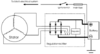 The permanent magnet generator system FIG 1.
A generator on a bike is producing this electrical power because it has a copper wire winding on the stator (the static part of the generator) that is located inside a varying magnetic field. The simplest generator uses a flywheel that runs on the crankshaft with a couple of magnets inside it. We call this flywheel with its built-in magnets the rotor.
Permanent magnet generator FIG 1.
The magnets themselves have north- and south-poles and the flywheel is rotating around the stator. The stator is a metal core with a lot of metal poles that have windings of copper-wire on them.Because the flywheel is rotating and there are north and south-poles inside it, the windings of the stator are exposed to first a north-pole, then a south-pole, then a north-pole again etc. This is the varying magnetic field that is needed to let the winding itself produce AC-current. The windings themselves are connected in a star (one winding has two ends and the three ends of the three different windings are connected together) so the stator has only three output wires emerging from it.
This generator-setup we call a permanent magnet generator. This is because the flywheel contains magnets that are magnetic all the time. The output of a certain stator is depending on the engine-speed (the higher the speed of the magnetic-field variation, the higher the stator-output), and the force of the magnetic field (which is constant). Basically the stator produces a certain output at a certain rpm.
Then the AC-current is led through the rectifier inside the regulator-rectifier-unit. The rectifier converts the three AC-phases to a single 14.4 Vdc output, a ground and a positive. Because the stator is producing power according to the engine-speed the stator-output is too high all the time. This would mean the output voltage of the regulator-rectifier would be way over 14.4 Vdc all the time, which would result in an overcharged battery and blowing electrical components on the bike that were meant to run on a voltage between 12 and 15 Vdc.
Luckily there is also a regulator-part inside a regulator-rectifier. The regulator looks at the DC-voltage across the battery-terminals and short-circuits a certain amount of power that is produced by the stator to ground. This is regulated constantly, so the output-voltage of the regulator-rectifier (which ideally is the same as the voltage across the battery-terminals) stays at 14.4 Vdc all the time. The permanent magnet generator-setup is not very efficient, but it is very simple and quite reliable. This explains why it is the most commonly used system on motorcycles. One of the problems with these systems is the short-circuiting of the excess power itself. This is done by the regulator-rectifier and this part has to dissipate the power that it shorts to ground, meaning it will get very hot. This is mostly because of the regulator and partly by the rectifier-diodes themselves that get hot just because of the current flowing through it. The regulator-rectifier internals need to be built so that the heat is transferred efficiently from the electronic components themselves to the housing of the unit, mostly equipped with cooling-fins. This is the most important bit in designing a regulator-rectifier for use in a permanent-magnet generator-setup.
The regulator-part of the regulator-rectifier needs to measure the DC-voltage somewhere in the system. On the cheapest built units (quite a lot of OEM ones) this is done not by measuring the DC-voltage in the DC-system, but by looking at the AC-voltage in between one stator-phase and the ground, and sometimes the excess power is shorted to ground from just one or two input-AC phases instead of all three phases that are regulated. The better built units measure the output-voltage of the unit itself and regulate the input AC accordingly by shorting more or less power to ground, an equal amount off all three phases.
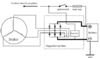
Permanent magnet generator FIG 2.
Some units use an extra input wire (FIG 2) to measure the DC-voltage.This wire normally is connected up trough the ignition-switch and not straight to the battery.So there is only a voltage on this lead if the ignition is turned on. This is done to make up for a voltage-drop that can occur because of a bad-connection in the leads from the regulator-rectifier output to the battery-terminals. These leads carry a high current and any bad connection here will result in a lower voltage over the battery-terminals.
The extra lead carries a much lower current and the result of this setup is that the output-voltage of the regulator-rectifier will be higher, the same DC-voltage as the voltage-drop in the high current leads plus 14.4 Vdc. It has the advantage that the battery will charge, in spite of a bad connection, but has the disadvantage that the high-current leads can eventually burn out because of this, without the owner even noticing beforehand that there is a problem in the circuit.
One thing to keep in mind is that the output-power provided by the stator-winding is delivered in between the phases. The ground in the charging system is the negative output from the rectifier. The AC-part of the three phase system is floating from ground. This means that testing of the AC-output needs to be done IN BETWEEN two of the three phases, and not from one phase to ground.
The field controlled generator system
[ST1100 28 amp system, see maintenance free version description below]
The other system used on motorcycles is the field-controlled generator. The system itself works on the principles as a permanent magnet generator, the only big difference is that there are no permanent magnets but instead there is an electromagnet that provides the necessary magnetism. (This magnetism is normally called the "field") The electromagnet is a single big winding on a metal core that gets magnetized as soon as there is DC-current flowing through the winding, supplied by the battery. A car-generator basically uses the same system.
On most of the field-controlled systems this metal core has claw-poles and two slip rings. The whole thing rotates with the crankshaft, with the statorwinding (just like the permanent-magnet stator) around it. Imagine looking at the outer side of the rotor sideways. You will see two pieces of metal pressed together with a winding in between. When you apply battery-voltage across the sliprings, the rotor will behave like a big electromagnet, and the left-hand side of the rotor will be say a north-pole, then the right-hand side will be a south-pole. In the middle you can see the pieces overlapping, meaning when the rotor rotates there first will be a south-pole passing, then a north-pole, then a south-pole etc. This is the needed varying magnetic field for generating AC-current in the stator-winding. The three-phase AC output from the stator-winding is led through a rectifier (inside the regulator-rectifier-unit) to convert it to DC for charging the battery.
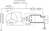 Switched Field
Regulation is done by the regulator-part of the regulator-rectifier. It senses the voltage in the bike’s electrical system and when the voltage is lower than 14.4 Vdc it switches on the field (it switches a 12Vdc supply across the sliprings). Then there is a magnetic field, so the stator will produce power. When the voltage in the bike’s system reaches over 14.4 Vdc the regulator senses that and just switches the field off. Then the voltage will drop because the stator doesn’t produce any power anymore (there is no varying magnetic field). When the voltage drops below app14.2 V, the regulator switches the field back on.
This is a constant process and the result of this is a constant voltage across the battery-terminals of 14.4 Vdc. Because there is no excess power produced by the stator, this system is very efficient. Counterside is that it is not as simple and small as a permanent magnet generator. The field winding normally has one side connected to the battery-positive through the ignition-switch. So there is only power for the field when the ignition is turned on. Regulation is done through the regulator-part of the regulator-rectifier by switching the ground for the field on or off. On some machines the set-up is the other way around, then one side of the field is connected to ground at all times, and the other side is switched on or off to a positive feed (through the ignition-switch) by the regulator.
The maintenance free field controlled generator [ST1100 28 amp system]
Some machines have a slightly different setup. Then the stator is located inside a cover, as well as the field winding in the middle of it. In between rotates an iron claw-pole driven by the engine. The claw-pole gets magnetized by the field winding and the system works like the field-controlled one as explained above. The difference is that the field does not rotate, so it doesn’t need to be powered through slip-rings and brushes, which makes it virtually maintenance-free. Counterside of this setup is the extra airgap between the fieldwinding and the claw-pole. Normally you have a very narrow airgap between rotor and stator that is needed to let the rotor rotate freely. This airgap needs to be as small as possible, the smaller the airgap, the more efficient the generator works. On this maintenance free system there is an extra airgap, so this system is less efficient.
The unit field controlled generator [ST1100 40 amp system]
The last variant of this system is a car-type generator that is bolted onto the bike's engine as a single unit. It is driven by the engine itself and has a built-in rectifier, and a built-in regulator, just like a car-generator.The only connections to it are the positive output-lead to the battery-plus and a supply-lead from the ignition-switch to the regulator inside, so the regulator can be turned on and off when the engine is not running, and it can sense the voltage on the bikes electrical system on this wire. Sometimes there is a third wire coming from it, which is a ground-lead, to the frame or the battery-negative. So because the rectifier and the regulator are built into the generator itself, there is only DC-voltage (14.4 Vdc) coming from this generator.
~~~~~~~~~~~~~~~~~~~~~~~~~~~~~~~~~~~~
Jun11 - http://www.electrosport.com/technical-resources/technical-articles/how-motorcycle-charging-system-works
Technical Article: How a Motorcycle Charging System Works
The basics of a charging system
On almost every motorcycle you will find a battery, used for providing power for starting the bike and for buffering an amount of electric energy. The battery itself is charged by a generator driven by the engine, and as long as the engine is running there will be a current flowing through the battery. The no load voltage of a fully charged battery is about 13 Vdc. For charging it the charging-system should provide a voltage of about 14.4 Vdc and this should be a constant voltage at all engine-speeds.
The generator itself is located in or on the engine, and on most bikes there is a separate regulator-rectifier-unit located somewhere on the frame. The reason for this is that almost all motorcycles are equipped with a three-phase AC (Alternating Current) generator, while the electrical system on the bike is a DC (Direct Current) system. The rectifier part inside the regulator-rectifier takes care of converting the AC-current to the DC-current the battery needs. The three-phase AC generator is used so often because it is much more efficient and reliable than a DC-generator. It can produce power for charging the battery even with the engine idling. The regulator part of the regulator-rectifier is used to regulate the output-voltage (to the battery) to the 14.4 Vdc that is needed.
The permanent magnet generator system FIG 1.A generator on a bike is producing this electrical power because it has a copper wire winding on the stator (the static part of the generator) that is located inside a varying magnetic field. The simplest generator uses a flywheel that runs on the crankshaft with a couple of magnets inside it. We call this flywheel with its built-in magnets the rotor.
Permanent magnet generator FIG 1.
The magnets themselves have north- and south-poles and the flywheel is rotating around the stator. The stator is a metal core with a lot of metal poles that have windings of copper-wire on them.Because the flywheel is rotating and there are north and south-poles inside it, the windings of the stator are exposed to first a north-pole, then a south-pole, then a north-pole again etc. This is the varying magnetic field that is needed to let the winding itself produce AC-current. The windings themselves are connected in a star (one winding has two ends and the three ends of the three different windings are connected together) so the stator has only three output wires emerging from it.
This generator-setup we call a permanent magnet generator. This is because the flywheel contains magnets that are magnetic all the time. The output of a certain stator is depending on the engine-speed (the higher the speed of the magnetic-field variation, the higher the stator-output), and the force of the magnetic field (which is constant). Basically the stator produces a certain output at a certain rpm.
Then the AC-current is led through the rectifier inside the regulator-rectifier-unit. The rectifier converts the three AC-phases to a single 14.4 Vdc output, a ground and a positive. Because the stator is producing power according to the engine-speed the stator-output is too high all the time. This would mean the output voltage of the regulator-rectifier would be way over 14.4 Vdc all the time, which would result in an overcharged battery and blowing electrical components on the bike that were meant to run on a voltage between 12 and 15 Vdc.
Luckily there is also a regulator-part inside a regulator-rectifier. The regulator looks at the DC-voltage across the battery-terminals and short-circuits a certain amount of power that is produced by the stator to ground. This is regulated constantly, so the output-voltage of the regulator-rectifier (which ideally is the same as the voltage across the battery-terminals) stays at 14.4 Vdc all the time. The permanent magnet generator-setup is not very efficient, but it is very simple and quite reliable. This explains why it is the most commonly used system on motorcycles. One of the problems with these systems is the short-circuiting of the excess power itself. This is done by the regulator-rectifier and this part has to dissipate the power that it shorts to ground, meaning it will get very hot. This is mostly because of the regulator and partly by the rectifier-diodes themselves that get hot just because of the current flowing through it. The regulator-rectifier internals need to be built so that the heat is transferred efficiently from the electronic components themselves to the housing of the unit, mostly equipped with cooling-fins. This is the most important bit in designing a regulator-rectifier for use in a permanent-magnet generator-setup.
The regulator-part of the regulator-rectifier needs to measure the DC-voltage somewhere in the system. On the cheapest built units (quite a lot of OEM ones) this is done not by measuring the DC-voltage in the DC-system, but by looking at the AC-voltage in between one stator-phase and the ground, and sometimes the excess power is shorted to ground from just one or two input-AC phases instead of all three phases that are regulated. The better built units measure the output-voltage of the unit itself and regulate the input AC accordingly by shorting more or less power to ground, an equal amount off all three phases.
Permanent magnet generator FIG 2.
Some units use an extra input wire (FIG 2) to measure the DC-voltage.This wire normally is connected up trough the ignition-switch and not straight to the battery.So there is only a voltage on this lead if the ignition is turned on. This is done to make up for a voltage-drop that can occur because of a bad-connection in the leads from the regulator-rectifier output to the battery-terminals. These leads carry a high current and any bad connection here will result in a lower voltage over the battery-terminals.
The extra lead carries a much lower current and the result of this setup is that the output-voltage of the regulator-rectifier will be higher, the same DC-voltage as the voltage-drop in the high current leads plus 14.4 Vdc. It has the advantage that the battery will charge, in spite of a bad connection, but has the disadvantage that the high-current leads can eventually burn out because of this, without the owner even noticing beforehand that there is a problem in the circuit.
One thing to keep in mind is that the output-power provided by the stator-winding is delivered in between the phases. The ground in the charging system is the negative output from the rectifier. The AC-part of the three phase system is floating from ground. This means that testing of the AC-output needs to be done IN BETWEEN two of the three phases, and not from one phase to ground.
The field controlled generator system
[ST1100 28 amp system, see maintenance free version description below]
The other system used on motorcycles is the field-controlled generator. The system itself works on the principles as a permanent magnet generator, the only big difference is that there are no permanent magnets but instead there is an electromagnet that provides the necessary magnetism. (This magnetism is normally called the "field") The electromagnet is a single big winding on a metal core that gets magnetized as soon as there is DC-current flowing through the winding, supplied by the battery. A car-generator basically uses the same system.
On most of the field-controlled systems this metal core has claw-poles and two slip rings. The whole thing rotates with the crankshaft, with the statorwinding (just like the permanent-magnet stator) around it. Imagine looking at the outer side of the rotor sideways. You will see two pieces of metal pressed together with a winding in between. When you apply battery-voltage across the sliprings, the rotor will behave like a big electromagnet, and the left-hand side of the rotor will be say a north-pole, then the right-hand side will be a south-pole. In the middle you can see the pieces overlapping, meaning when the rotor rotates there first will be a south-pole passing, then a north-pole, then a south-pole etc. This is the needed varying magnetic field for generating AC-current in the stator-winding. The three-phase AC output from the stator-winding is led through a rectifier (inside the regulator-rectifier-unit) to convert it to DC for charging the battery.
Switched FieldRegulation is done by the regulator-part of the regulator-rectifier. It senses the voltage in the bike’s electrical system and when the voltage is lower than 14.4 Vdc it switches on the field (it switches a 12Vdc supply across the sliprings). Then there is a magnetic field, so the stator will produce power. When the voltage in the bike’s system reaches over 14.4 Vdc the regulator senses that and just switches the field off. Then the voltage will drop because the stator doesn’t produce any power anymore (there is no varying magnetic field). When the voltage drops below app14.2 V, the regulator switches the field back on.
This is a constant process and the result of this is a constant voltage across the battery-terminals of 14.4 Vdc. Because there is no excess power produced by the stator, this system is very efficient. Counterside is that it is not as simple and small as a permanent magnet generator. The field winding normally has one side connected to the battery-positive through the ignition-switch. So there is only power for the field when the ignition is turned on. Regulation is done through the regulator-part of the regulator-rectifier by switching the ground for the field on or off. On some machines the set-up is the other way around, then one side of the field is connected to ground at all times, and the other side is switched on or off to a positive feed (through the ignition-switch) by the regulator.
The maintenance free field controlled generator [ST1100 28 amp system]
Some machines have a slightly different setup. Then the stator is located inside a cover, as well as the field winding in the middle of it. In between rotates an iron claw-pole driven by the engine. The claw-pole gets magnetized by the field winding and the system works like the field-controlled one as explained above. The difference is that the field does not rotate, so it doesn’t need to be powered through slip-rings and brushes, which makes it virtually maintenance-free. Counterside of this setup is the extra airgap between the fieldwinding and the claw-pole. Normally you have a very narrow airgap between rotor and stator that is needed to let the rotor rotate freely. This airgap needs to be as small as possible, the smaller the airgap, the more efficient the generator works. On this maintenance free system there is an extra airgap, so this system is less efficient.
The unit field controlled generator [ST1100 40 amp system]
The last variant of this system is a car-type generator that is bolted onto the bike's engine as a single unit. It is driven by the engine itself and has a built-in rectifier, and a built-in regulator, just like a car-generator.The only connections to it are the positive output-lead to the battery-plus and a supply-lead from the ignition-switch to the regulator inside, so the regulator can be turned on and off when the engine is not running, and it can sense the voltage on the bikes electrical system on this wire. Sometimes there is a third wire coming from it, which is a ground-lead, to the frame or the battery-negative. So because the rectifier and the regulator are built into the generator itself, there is only DC-voltage (14.4 Vdc) coming from this generator.
~~~~~~~~~~~~~~~~~~~~~~~~~~~~~~~~~~~~
Last edited:
" The maintenance free field controlled generator [ST1100 28 amp system]
Some machines have a slightly different setup. Then the stator is located inside a cover, as well as the field winding in the middle of it. In between rotates an iron claw-pole driven by the engine. The claw-pole gets magnetized by the field winding and the system works like the field-controlled one as explained above. The difference is that the field does not rotate, so it doesn’t need to be powered through slip-rings and brushes, which makes it virtually maintenance-free. Counterside of this setup is the extra air gap between the field winding and the claw-pole. Normally you have a very narrow air gap between rotor and stator that is needed to let the rotor rotate freely. This air gap needs to be as small as possible, the smaller the air gap, the more efficient the generator works. On this maintenance free system there is an extra air gap, so this system is less efficient. "
Interesting & weird. The stationary field must induce a voltage in the rotating rotor that results in current and a magnetic field in the rotor. Then the rotor field cuts the stator windings and induces a voltage in the stator. Not very efficient. I have never heard of this method before - I learned something.
Usually alternators that use a VRR employ a PM rotor, not a "claw" type rotor.
A PM rotor is just a big magnet, that looks like this :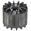