FIX THIS FIRST Red wire bypass is on my list of To Dos because there has been some melting of the 4P connector around the red wire (don't know if it's recent or from years prior--I had never looked before this recent issue came up). I hadn't considered that as a potential cause of the current low voltage problem.

Regulated Voltage/Amp check
- Thread starter tkhelm
- Start date
The good news is that I completed the Red Wire By-Pass; the bad news is that it didn't change the situation with low/no voltage coming from the VRR--same as before. I also had the battery load tested at Interstate Battery and they said it was fine.
I swapped back to my old VRR just to see if I could find anything different between the two of them. Nothing that I could find was different--I'm still getting 35V AC at all three yellow wires at the 6P connector to the VRR with the engine at idle speed, but the red/white wire at the 6P shows the same 11.6V DC as I measured at the battery terminals, again while the engine is idling.
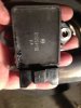
This time I noticed that my old VRR was quite hot after maybe 5 mins of running the engine. The STOC loaner VRR does not get hot. Although I previously thought the oily stuff on my old VRR was from somewhere else, now that I have a clean one to compare to I realized that it's probably meltage (left bottom quadrant in the picture), so my VRR is probably toast:
I'm sure it's possible that whatever my problem is toasted the STOC loaner VRR from the first instant I had it on, but is that likely? Again, there's no sign of heat or damage to the STOC loaner. but everything seems to be fine up to the point of the AC entering the VRR...but the right DC doesn't come out.
One thing I can think to do next is pull the red/white wire out of the 6P and test the VRR output on the male paddle with the multimeter probe while the engine is running. With no connection to the battery I should be able to see if the VRR is putting any DC out at all. However, I haven't been able to dislodge the red/white wire's female paddle from the 6P connector as easily as I got the red wire out of the 4P for the Red Wire By-pass. What's the trick to doing that without ruining the 6P?
I swapped back to my old VRR just to see if I could find anything different between the two of them. Nothing that I could find was different--I'm still getting 35V AC at all three yellow wires at the 6P connector to the VRR with the engine at idle speed, but the red/white wire at the 6P shows the same 11.6V DC as I measured at the battery terminals, again while the engine is idling.
This time I noticed that my old VRR was quite hot after maybe 5 mins of running the engine. The STOC loaner VRR does not get hot. Although I previously thought the oily stuff on my old VRR was from somewhere else, now that I have a clean one to compare to I realized that it's probably meltage (left bottom quadrant in the picture), so my VRR is probably toast:
I'm sure it's possible that whatever my problem is toasted the STOC loaner VRR from the first instant I had it on, but is that likely? Again, there's no sign of heat or damage to the STOC loaner. but everything seems to be fine up to the point of the AC entering the VRR...but the right DC doesn't come out.
One thing I can think to do next is pull the red/white wire out of the 6P and test the VRR output on the male paddle with the multimeter probe while the engine is running. With no connection to the battery I should be able to see if the VRR is putting any DC out at all. However, I haven't been able to dislodge the red/white wire's female paddle from the 6P connector as easily as I got the red wire out of the 4P for the Red Wire By-pass. What's the trick to doing that without ruining the 6P?
Last edited:
Oh, also, I tried jumpering the red/white from the 6P at the VRR direct to the positive batter terminal but saw no difference, not even a blip on the voltmeter when I connected/disconnected.
One thing I can think of doing next is to see if anyone near me with an ST1100 would act as a control and put the STOC loaner VRR on their working bike and see if it operates properly. Any other ideas?
Thank very much for all the help...I'd be totally lost without all this support!
One thing I can think of doing next is to see if anyone near me with an ST1100 would act as a control and put the STOC loaner VRR on their working bike and see if it operates properly. Any other ideas?
Thank very much for all the help...I'd be totally lost without all this support!
Hi resistance results in voltage dropRed wire bypass is on my list of To Dos because there has been some melting of the 4P connector around the red wire (don't know if it's recent or from years prior--I had never looked before this recent issue came up). I hadn't considered that as a potential cause of the current low voltage problem.
Would resistance downstream at the 4P connector cause the voltage to be low at the 6P connector/VRR output? Or should it read normal (>14V) out of the VRR and then read differently after the point that is damaged, if that's whats going on?
I'm still trying to get my head around the basics but I had thought corrosion or a burnt but functioning wire would lead to high voltage not low (and eventually do damage to something).
") .
.I would completely change out that connector for a new one or hard wire it. When one connection appears to be a problem, all the others in the same connector become suspect. Eliminate that from the problem with either a shiny new one or none at all until you clear the problem. Indications of heat, melting, discolored metal terminals are all "red flags" in any electrical circuit. The higher the current (amps) the more sensitive these become. JMHO
One thing I can think to do next is pull the red/white wire out of the 6P and test the VRR output on the male paddle with the multimeter probe while the engine is running. With no connection to the battery I should be able to see if the VRR is putting any DC out at all. However, I haven't been able to dislodge the red/white wire's female paddle from the 6P connector as easily as I got the red wire out of the 4P for the Red Wire By-pass. What's the trick to doing that without ruining the 6P?
After a week+ of work and home obligations I'm finally getting back to this. It seems I have power coming out of the STOC loaner VRR at the 6P on the red/white wire and I have continuity and low resistance (o.3 ohm) on the red/white wire from the 6P to the ignition relay. But I don't have any change in volts at the battery when the engine is on. So I now suspect a problem either at the ignition relay or on the wire from the back of the ignition relay to the battery. That's a pretty sturdy looking wire, so perhaps it's more likely the problem is the relay switch itself. I don't see anything in my Honda service manual about testing the functionality of the ignition relay. With the engine off, that circuit (red/white from VRR to large black from IR to battery) should be blocked, but with the engine on I'm not sure how to verify that the circuit is open and functioning properly. It's quite a reach to get around back of the IR with a multimeter probe.
Am I likely on the right track, and is there a good way to check this?
Am I likely on the right track, and is there a good way to check this?
Last edited:
For future reference and general FYI, I just ran across an interesting 'dissertation' on replacing the VRR (part #31600-MS2-601) that includes descriptions and sources for alternative VRRs that will apparently work on the ST1100:
http://www.vitri.es/datos/regulador-cbr1000f.pdf
There is also a discussion of the ElectroSport ESR230 in this forums archives here that quotes a rep at ElectoSport: "Our ESR230 has a built in over-current and over-temperature safety circuit built in as part of the design which prevents failure due to a bad field rotor. This is a major improvement over the stock setup. The heatsink used in ESR230 gets rid of internal heat quickly and efficiently which makes for a very reliable unit."
John OoSTerhuis
Life Is Good!
The starter relay doesn't have anything to do with getting charging system current to the battery. Connecting the red/white lead from the VRR to that post on the relay is simply a convenient place to tie into the battery. You can simply connect the red/white lead directly to the battery pos + post if you like (as is done in many 40amp upgrades). IIRC I've previously mentioned this.
BTW, how does the main fuse look?
John
BTW, how does the main fuse look?
John