
- Joined
- Mar 18, 2006
- Messages
- 2,832
- Age
- 70
- Location
- Ilkley, W Yorkshire, UK
- Bike
- 2013 ST1300 A9
- 2024 Miles
- 000679
- STOC #
- 2570
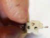
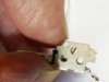
A detailed look at the inner workings of the front brake light switch, and how to to put the tiny pieces back together again.
This is switch is from an ST1300, but the exact same part is used on the ST1100 as well. The other day, my brake light switch failed. As far as I can tell, it was due to build up of surface corrosion, which made the parts move out of alignment and fall apart. I bought a new one, but then wondered if the old one could have been fixed. So now I have a spare !
Probably not any time soon, but one day, you might find this useful.
There are a lot of images in this post. They may not all load before the server times out - if you get a message like "1234567890112.png" or "fr brake switch 01.png" with a small picture icon alongside, then right click on the icon and select the option to download the image. (for a PC). I don't know what to do if you use an Apple. If someone can let me know, I'll put that in here.
So Corvid-19 is keeping the bike in the garage, where is has been for nearly all winter. I did the full winter service while it was too icy to get out, and just as the weather was picking up and I started looking longingly for an opportunity to go and ride, we were locked down. So I did the fork seals and front forks to give myself a few more headaches.
On Wednesday, the lockdown restrictions were lifted slightly. We could now drive/ride out to get fresh air and open spaces. But not into Wales. Or into Scotland. Nor the Lake District, Peak District. Exmoor and Dartmoor are out of bounds. So the leader of the entire UK says one thing. The places concerned say another. Hmm. I remember seeing new teachers who were unable to control a class when they first started. I can't think why that thought sprang into my mind.
So anyway, there were places that I could go. Tuesday night I got the bike ready for a ride, did a quick check that all was OK, and the brake lights were not working. What ? They worked two weeks ago. The front brake light switch had failed while it was sitting in the garage.
I did get help from an on-line video, and it did a good job of showing what to do, but it was vague in many places, so I had to work out the fine detail, and I couldn't get the bits together in the way that the video showed. It just kept falling apart. Judging by the number of edits, so did his.
So I devised my own method, and this works for me. And I took it apart again to take the photos of it going back together. Click the images to get a slightly larger version.
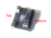
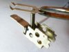
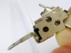
First of all a look at the casing and how to get that apart.
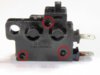
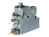
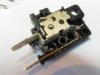
The three circled parts are plastic studs, which 'pop' into a locked position when they are inserted. Prying the body apart will release (or break) them. Pushing down with a small flat shaft on the end of the stud that is circled will help. Really, I suspect that all three need to be pressed simultaneously. One of mine broke, the others popped easily once I had a place to insert a broad blade into the join.
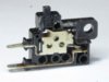
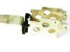
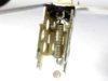
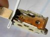
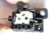
The last photo of the three shows the bottom terminal as being static. The top part is the bit with the moving parts. behind the metal plate with the three holes is the moving contact (which can be seen in contact with the static contact), the lever that is in contact with the plastic switch at the top, and a coiled spring. These three parts were floating around.
All of the parts had surface corrosion. I cleaned them all up once I had the bits separated.
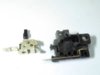
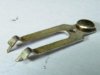
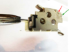
There are ten pieces in all. 3 parts that make up the rocker motion inside the cage, a plastic button, the two terminal parts, two tiny pieces onto which the spring is attached and the top and bottom part of the casing. They will all gently pry out of the plastic casing.
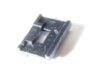
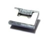
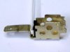
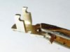
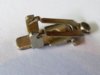
The cage is attached to the upper terminal blade.
Inside the cage
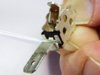
Inside is a rocker mechanism and the moving contact and spring (the electrical contact is where the tweezers are holding the part).
Also there is a spring plate, and a plastic moulding for the spring plate.
Identifying how the fixed parts fit back together.
The plastic moulding for the spring plate fits at the rear of the cage. The photo above shows the other face from the previous photo.
This face is positioned facing towards the cage as shown below. That ridge at the bottom fits inside the cages sides.
The photo above shows the plastic part being offered up to the rear of the cage to help identify the orientation.
The metal spring plate mates with the other side of the moulding, with the tab poking through the hole.
Get a piece of packing handy - a strip of folded card, or in my case, plastic.
This is how the spring plate and the moulding fit together as one part into the rear of the cage.
The packing piece stops them from falling out again for the time being, so that we don't have to worry about them.
The packing will be removed before the assembled unit fits back into the main plastic case.
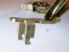
Identifying how the 3 moving parts fit together.
There are 3 key components left. The switch rocker, the contact strip and the spring.
It is difficult to see how these fit together when trying to assemble them inside the cage, so first of all, a bit of practice.
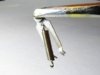
The switch rocker on the left (held by tweezers). The contact strip on the right. The electrical contact point is the shiny circular blob at the right hand end.
Note the V bend and the funny shaped tags at the left hand end. You need to be able to recognise those later.

This is how two these two parts fit together. When you put these inside the cage the assembly will be the other way up, the contact strip will be placed in first and the switch rocker will be put on top.
It is worthwhile turning the above assembly the other way up - put the contact strip on the worktop and position the rocker on the contact strip - just for practice .
When you do it for real, it will be difficult to see, and there will be a spring attached to the contact strip in that hole at the right hand end !
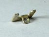
So here is the contact strip with the spring attached.
Note that in this photo the spring is hooked on from the wrong side try not to make this mistake. The correct way is shown below.
The right hand photo shows the fitting of the switch rocker into the cage. This fits in loosely as the last item, but note the metal lugs and the notches in the side of the rocker.
The only way that it will fit properly is by aligning the notches with the lugs (as shown) and lowering it down. It can then slide forwards or backwards into its correct position.
It is worth practicing these before trying to put the 3 parts together.
Ok - so now we can fit the three parts inside the cage.
First the spring and the contact strip.

This is the correct way round. The the contact facing down, the 'V' pivot pointing down, and those funny tags on the left point upwards. Hook the spring as shown.
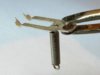
We are going to go fishing and catch ourselves a cage.
The hook on the other end of the spring needs to catch the hole in the spring plate that is held in place in the cage.
Once you have both ends of the spring attached, keep the spring in slight tension, to prevent either end of the spring from dropping out of the hole.
It doesn't need much - gravity will do.
Looking at the above photo, we need to hold the cage by its sides and move the tweezers away to the right and in a clockwise direction to keep some tension on the spring so that the contact strip and spring are on the bottom of the cage. The contact strip stays horizontal, the spring rotates through 90 degrees
Like this. This photo shows the cage from above. Safe to let go briefly, as long as the assembly isn't knocked. The spring will hook off at either end very easily. Best to keep it in tension.
Just check - the actual contact point is facing away from the camera. What you can see is the copper coloured rear of the electrical contact. Also , those funny tangs on the end of the contact strip are pointing towards the camera, with the Vee pointing down.
Whatever happens next, keep tension on that spring as the switch rocker is manoeuvred into position. This bit is a little tricky. In the photos that follow, where you see my thumb, I am holding the contact point at the bottom of the above photo and pulling back on it slightly - not to stretch the spring, but to keep tension on it to stop the hooks on each end of the spring from falling out of their holes.
By pressing down on the contact at the bottom of the photo, I can raise the tags at the other end of the contact strip to help manoeuvre them into a better position.
What we are aiming for is this connection between the rocker and the funny tags on the end of the contact strip. But of course, this image is now upside down, but you can see how the parts fit together. You practiced this earlier.
So - offer the rocker up to the cage. The left hand picture shows a starting position. My thumb is pulling back on the contact point of the contact strip, to keep the spring in tension.
But two things need to happen:
The rocker legs need to engage with those funny tags on the contact strip, and the rocker itself needs to be positioned underneath those metal lugs.
To do this, it is necessary to press down on the contact to raise the funny tags. This enables you to see what you are doing with the rocker and to get the rocker to slip past those lugs.
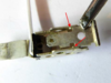
This is it with the rocker in its final position. Note the right hand end of the rocker should seat where the green arrow is pointing. (Which it is).
The red position is useful for seating the right hand end of the rocker when it first comes under tension of the spring.
But now with the rocker in position and its left hand lugs in the position shown by the green arrow in the picture above, you can let go of everything. It is all held together by the springs tension.
So once it is like this, you can check it out. Press down on the end of the switch rocker, and the contact at the right hand side in the photo should spring into the up position. Release, and it springs down again. There is never a half way position.
Remove the packing card that you used to hold the spring plate in position. It is now held by the spring.
The entire assembly can be inserted back into the plastic case.
Offer it up to the mouldings, but note before you press it down, that the contact at the back needs to be moved. Press on the tag of the switch rocker at the top of the cage to lift it - don't move the contact itself. That may relieve the tension on the spring and dislodge the funny locating tags from the rocker.
Insert the plastic button for the switch.
Close it up. If you managed to break one of more of the plastic retaining rivets when prising the pieces apart, then you might need to apply some glue. But check the operation of the switch and the electrical connections at the blades before doing so. Note that this switch is normally closed. The brake lever holds the button in, until you apply the brakes, when they spring closed.
If using superglue, do NOT use the very thin stuff. it will flow everywhere before it sets. I like the brushable thick Gorilla cyano glue for this reason. A thin layer just where it is needed, close up the top half and clamp the two parts together where glue has been applied to let it set. Try very hard to avoid getting glue anywhere near the push button !
This is switch is from an ST1300, but the exact same part is used on the ST1100 as well. The other day, my brake light switch failed. As far as I can tell, it was due to build up of surface corrosion, which made the parts move out of alignment and fall apart. I bought a new one, but then wondered if the old one could have been fixed. So now I have a spare !
Probably not any time soon, but one day, you might find this useful.
There are a lot of images in this post. They may not all load before the server times out - if you get a message like "1234567890112.png" or "fr brake switch 01.png" with a small picture icon alongside, then right click on the icon and select the option to download the image. (for a PC). I don't know what to do if you use an Apple. If someone can let me know, I'll put that in here.
So Corvid-19 is keeping the bike in the garage, where is has been for nearly all winter. I did the full winter service while it was too icy to get out, and just as the weather was picking up and I started looking longingly for an opportunity to go and ride, we were locked down. So I did the fork seals and front forks to give myself a few more headaches.
On Wednesday, the lockdown restrictions were lifted slightly. We could now drive/ride out to get fresh air and open spaces. But not into Wales. Or into Scotland. Nor the Lake District, Peak District. Exmoor and Dartmoor are out of bounds. So the leader of the entire UK says one thing. The places concerned say another. Hmm. I remember seeing new teachers who were unable to control a class when they first started. I can't think why that thought sprang into my mind.
So anyway, there were places that I could go. Tuesday night I got the bike ready for a ride, did a quick check that all was OK, and the brake lights were not working. What ? They worked two weeks ago. The front brake light switch had failed while it was sitting in the garage.
I did get help from an on-line video, and it did a good job of showing what to do, but it was vague in many places, so I had to work out the fine detail, and I couldn't get the bits together in the way that the video showed. It just kept falling apart. Judging by the number of edits, so did his.
So I devised my own method, and this works for me. And I took it apart again to take the photos of it going back together. Click the images to get a slightly larger version.
First of all a look at the casing and how to get that apart.
The three circled parts are plastic studs, which 'pop' into a locked position when they are inserted. Prying the body apart will release (or break) them. Pushing down with a small flat shaft on the end of the stud that is circled will help. Really, I suspect that all three need to be pressed simultaneously. One of mine broke, the others popped easily once I had a place to insert a broad blade into the join.
The last photo of the three shows the bottom terminal as being static. The top part is the bit with the moving parts. behind the metal plate with the three holes is the moving contact (which can be seen in contact with the static contact), the lever that is in contact with the plastic switch at the top, and a coiled spring. These three parts were floating around.
All of the parts had surface corrosion. I cleaned them all up once I had the bits separated.
There are ten pieces in all. 3 parts that make up the rocker motion inside the cage, a plastic button, the two terminal parts, two tiny pieces onto which the spring is attached and the top and bottom part of the casing. They will all gently pry out of the plastic casing.
The cage is attached to the upper terminal blade.
Inside the cage
Inside is a rocker mechanism and the moving contact and spring (the electrical contact is where the tweezers are holding the part).
Also there is a spring plate, and a plastic moulding for the spring plate.
Identifying how the fixed parts fit back together.
The plastic moulding for the spring plate fits at the rear of the cage. The photo above shows the other face from the previous photo.
This face is positioned facing towards the cage as shown below. That ridge at the bottom fits inside the cages sides.
The photo above shows the plastic part being offered up to the rear of the cage to help identify the orientation.
The metal spring plate mates with the other side of the moulding, with the tab poking through the hole.
Get a piece of packing handy - a strip of folded card, or in my case, plastic.
This is how the spring plate and the moulding fit together as one part into the rear of the cage.
The packing piece stops them from falling out again for the time being, so that we don't have to worry about them.
The packing will be removed before the assembled unit fits back into the main plastic case.
Identifying how the 3 moving parts fit together.
There are 3 key components left. The switch rocker, the contact strip and the spring.
It is difficult to see how these fit together when trying to assemble them inside the cage, so first of all, a bit of practice.
The switch rocker on the left (held by tweezers). The contact strip on the right. The electrical contact point is the shiny circular blob at the right hand end.
Note the V bend and the funny shaped tags at the left hand end. You need to be able to recognise those later.
This is how two these two parts fit together. When you put these inside the cage the assembly will be the other way up, the contact strip will be placed in first and the switch rocker will be put on top.
It is worthwhile turning the above assembly the other way up - put the contact strip on the worktop and position the rocker on the contact strip - just for practice .
When you do it for real, it will be difficult to see, and there will be a spring attached to the contact strip in that hole at the right hand end !
So here is the contact strip with the spring attached.
Note that in this photo the spring is hooked on from the wrong side try not to make this mistake. The correct way is shown below.
The right hand photo shows the fitting of the switch rocker into the cage. This fits in loosely as the last item, but note the metal lugs and the notches in the side of the rocker.
The only way that it will fit properly is by aligning the notches with the lugs (as shown) and lowering it down. It can then slide forwards or backwards into its correct position.
It is worth practicing these before trying to put the 3 parts together.
Ok - so now we can fit the three parts inside the cage.
First the spring and the contact strip.
This is the correct way round. The the contact facing down, the 'V' pivot pointing down, and those funny tags on the left point upwards. Hook the spring as shown.
We are going to go fishing and catch ourselves a cage.
The hook on the other end of the spring needs to catch the hole in the spring plate that is held in place in the cage.
Once you have both ends of the spring attached, keep the spring in slight tension, to prevent either end of the spring from dropping out of the hole.
It doesn't need much - gravity will do.
Looking at the above photo, we need to hold the cage by its sides and move the tweezers away to the right and in a clockwise direction to keep some tension on the spring so that the contact strip and spring are on the bottom of the cage. The contact strip stays horizontal, the spring rotates through 90 degrees
Like this. This photo shows the cage from above. Safe to let go briefly, as long as the assembly isn't knocked. The spring will hook off at either end very easily. Best to keep it in tension.
Just check - the actual contact point is facing away from the camera. What you can see is the copper coloured rear of the electrical contact. Also , those funny tangs on the end of the contact strip are pointing towards the camera, with the Vee pointing down.
Whatever happens next, keep tension on that spring as the switch rocker is manoeuvred into position. This bit is a little tricky. In the photos that follow, where you see my thumb, I am holding the contact point at the bottom of the above photo and pulling back on it slightly - not to stretch the spring, but to keep tension on it to stop the hooks on each end of the spring from falling out of their holes.
By pressing down on the contact at the bottom of the photo, I can raise the tags at the other end of the contact strip to help manoeuvre them into a better position.
What we are aiming for is this connection between the rocker and the funny tags on the end of the contact strip. But of course, this image is now upside down, but you can see how the parts fit together. You practiced this earlier.
So - offer the rocker up to the cage. The left hand picture shows a starting position. My thumb is pulling back on the contact point of the contact strip, to keep the spring in tension.
But two things need to happen:
The rocker legs need to engage with those funny tags on the contact strip, and the rocker itself needs to be positioned underneath those metal lugs.
To do this, it is necessary to press down on the contact to raise the funny tags. This enables you to see what you are doing with the rocker and to get the rocker to slip past those lugs.
This is it with the rocker in its final position. Note the right hand end of the rocker should seat where the green arrow is pointing. (Which it is).
The red position is useful for seating the right hand end of the rocker when it first comes under tension of the spring.
But now with the rocker in position and its left hand lugs in the position shown by the green arrow in the picture above, you can let go of everything. It is all held together by the springs tension.
So once it is like this, you can check it out. Press down on the end of the switch rocker, and the contact at the right hand side in the photo should spring into the up position. Release, and it springs down again. There is never a half way position.
Remove the packing card that you used to hold the spring plate in position. It is now held by the spring.
The entire assembly can be inserted back into the plastic case.
Offer it up to the mouldings, but note before you press it down, that the contact at the back needs to be moved. Press on the tag of the switch rocker at the top of the cage to lift it - don't move the contact itself. That may relieve the tension on the spring and dislodge the funny locating tags from the rocker.
Insert the plastic button for the switch.
Close it up. If you managed to break one of more of the plastic retaining rivets when prising the pieces apart, then you might need to apply some glue. But check the operation of the switch and the electrical connections at the blades before doing so. Note that this switch is normally closed. The brake lever holds the button in, until you apply the brakes, when they spring closed.
If using superglue, do NOT use the very thin stuff. it will flow everywhere before it sets. I like the brushable thick Gorilla cyano glue for this reason. A thin layer just where it is needed, close up the top half and clamp the two parts together where glue has been applied to let it set. Try very hard to avoid getting glue anywhere near the push button !
Last edited:
")