SkitzyMcGee
Mechanical Mastermind
Preface-
———————————————————————————
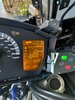
This is an issue I’ve seen with MANY ST1300s online, as well as on my own 2 personal bikes. (Maybe you've seen or experienced this as well!) The LCDs have a tendency to get yellow sunspots if left out in the sunlight for seemingly ANY amount of time. Like many ST owners I have too much time on my hands, as well as a neurotic yearning for "perfection". This causes many of us to buy entirely new instrument clusters to remedy this small issue. As parts for these beautiful bikes become more and more scarce, this wasteful use of entire instrument clusters is going to come back to bite us. But with a bit of time (2-4 hours) and care, you can save yourself 100s of dollars and keep the CORRECT mileage for your bike. Also, frankly, I wasn’t satisfied with the videos and guides that I found online for this procedure.
It is for these reasons that I have created this guide. To as simply and as quickly as possible, repair rather than replace the LCD inside of the dashboard instrument cluster.
Now I warn you, this is a “mildly” dangerous procedure. But if taken slowly and with appropriate caution, I know you can do it!
(I’m an idiot and I did it successfully to both my ST1300s, as well as on my Aprilia Falco)
To keep this guide short-ish, I will not explain how to remove the instrument cluster dashboard from the Bike, as there are already many wonderful guides on the forum that will show you how to accomplish that.
LINK TO DASHBOARD REMOVAL GUIDE
———————————————————————————
REQUIRED TOOLS AND MATERIALS-
———————————————————————————
This particular guide will focus on taking the instrument cluster itself apart (as little as possible) to remove the LCD unit and repairing the sun damaged LCD display itself with a sheet of LCD polarizing film.
To complete this process you will need-
Sharp scissors
A Screwdriver with PH2 Phillips bit
(I prefer a 1/4in ratchet but that’s just me.)
Pliers (Needle nosed preferred, though I used regular pliers.)
Plastic pry tool
Razor blade with a razor blade holder
Rubbing alcohol (preferably 70% or higher)
Cloth (for rubbing alcohol)
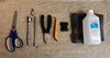
And of course, LCD polarizing film - Here is a link to exactly what I bought on Amazon.
But most importantly for this endeavor, you will need PATIENCE.
———————————————————————————
DISSASEMBLY OF THE INSTRUMENT CLUSTER-
———————————————————————————
Like I said earlier, we will start with the instrument cluster out of the bike and on a table. (Using a tablecloth will help stop the screws from running away on you.)
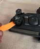
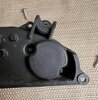
Begin by using your plastic pry tool to pop off the headlight adjustment knob on the left side of the front of the unit. (Mine gave me a surprisingly hard time, so be careful not to break yours.)
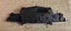
Now flip the unit over and remove the 9x PH2 screws around the perimeter. (These will be the ones with the larger heads.)
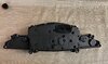
Then remove the two smaller headed PH2 screws behind the headlight adjustment knob. (Place them with the adjuster knob so you know where and what they are.)
Carefully separate the front and back housings of the instrument cluster by pulling on the edges of the front housing.
(If you’re having too much trouble, you might’ve forgotten a screw!)
Front and back half successfully separated!
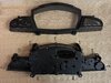
Set the front half of the unit in a safe place to the side.
Now remove the 12x smaller headed screws on the back half of the unit.
After removing those 12 screws, the speedometer and tachometer portion of the unit will drop out so be careful!
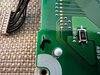
Flip the unit over and carefully unplugged the idiot lights, headlight adjuster, and trip buttons.
(All the other guides I’ve seen online have had you remove the screws to the idiot light, buttons and headlight adjuster PCBs but that’s just a waste of your time that incurs even more danger.)
Now, while holding the unit face up, place your left hand on the Speedo/tach dial cover, then with your right hand flip the entire unit over.
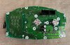
The main PCB should then fall out with no force required.
Set the main PCB down on its face.
(Again, remember to be gentle as the speedometer and tachometer stopper pins are INCREDIBLY easy to break.)
(Every other guide I’ve seen online will have you take off the speedo and tach needles, and remove the entire dial cover. Lucky for you this is an unnecessary step! Also, by not removing the needles, this keeps your speedometer and tachometer perfectly accurate.)
There are four metal flanges on the rear of the LCD unit that you need to bend straight so that they fit through the PCB. (This is where you use your pliers.)
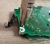
Once you have bent all 4 metal flanges completely straight, gently push on the flanges until they are all flush with the PCB.
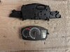
The front dial cover is flexible enough for you to slip the LCD unit out and to the right. (It’s flexible, but still breakable. Be careful.)
You should now have the LCD assembly separated from the main PCB and dial cover. Place the main PCB in a safe space off to the side.
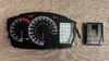
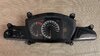
Now with the LCD assembly separated, we can get a real good look at the damage.
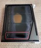
Begin by removing the white plastic LED diffuser bracket on the back of the LCD assembly. It should lift away with no force.
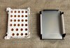
Then proceed with removing the black metal bracket surrounding the LCD. Keep in mind that the LCD unit is glued on the edges to this metal bracket. So it will require SOME force.
(Just use your hands for this part, using tools to pry will only risk damage to the LCD unit.)

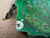
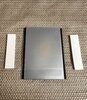
There are two white conductive rubber strips lightly glued to the back edges of the LCD unit. Your main PCB communicates with the LCD via these conductive rubber strips, so make sure to keep them clean. Gently peel these off and place them with the other parts.
You will now be holding just the LCD unit and the “melted/bad” polarized layers. Now this is where the razor blades and patience comes in.
(This is gentle reminder of how thin and fragile the part we are working with is.)
———————————————————————————
REMOVAL OF THE OLD POLARIZATION LAYERS-
———————————————————————————
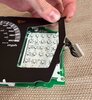
You will now start peeling off the polarization layers on the front AND back of the LCD unit.
Before you begin, here are a few tips from my personal experience in order to save your day and LCD-
1. You will notice that there are two pieces of glass that make up the LCD unit. A slightly larger piece of glass (front glass) and a smaller piece (rear glass). Since the edges of the front glass are obscured by the black metal bracket, an accidental chip on the front glass is less dangerous than a chip on the rear glass. (Though chipping the front glass should still be avoided at all costs.)
2. The smaller piece of “glass” (on the back side) is the LCD display itself. (This is where you should take most of your care and time.)
3. When using your razor blade, be VERY careful when working around the EDGES, as even very little force with a razor blade can chip the LCD. For the safest results, it is best to use your razor blade, perpendicular to the edge you are working on.
4. If you do happen to make a small chip on the edge of the LCD, you MIGHT still be okay, depending on if the chip intrudes on the digits/icons. (Don’t ask me how I know...)
5. So long as you are not using a diamond tipped razor blade (If you are, where the hell did you get that?) the front glass and LCD WILL NOT be scratched by a steel razor blade.
(If you do see scratches, there is either another layer of polarization that you need to peel off, or there is still remaining old adhesive from the old polarization layers.)
6. With your razor blade peel up all four corners of the film, it really helps the layers to come off cleanly.
7. Wiggle the blade left to right rather than using brute force.
8. Don't cut towards yourself or your fingers.
———————————————————————————
Front polarization layer removed.
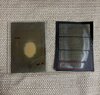
Back polarization layer removed.
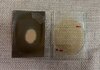
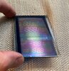
With JUST your razor blades (and patience) you should be able to get the LCD unit as clear as in the image below. Also in the right lighting, you will still be able to see the digits and icons. (Neat!)
Give the LCD unit a quick wipe down with your isopropyl alcohol and cloth.
———————————————————————————
NEW POLARIZATION LAYERS APPLICATON-
———————————————————————————
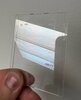
The correct orientation of both polarization layers is incredibly important to the proper function of the LCD, so listen carefully. (If you have an LCD TV nearby, it’ll be useful right about...now.)
We will apply the rear polarization layer first. This is the layer on the back of the ACTUAL LCD (The smaller piece of glass).
Orient the polarization film so that in the vertical position it blocks light from your LCD TV. Like so-

Cut a piece of polarizer film that is slightly larger than the rear (smaller) piece of glass. This will allow you some wiggle room during the application of the polarization film to the glass. (I will tell you how to take care of the overhanging polarizer film in a moment)
Remember that any "under coverage" will be visible in the final product as a bright spot.
(Which you don’t want, unless you just really enjoy doing this for some reason...)
Before applying a polarization layer it’s a really good idea to wash your hands with soap. Also, with a piece of plastic or something create a little "roof" that your hands can work under, this can help stop dust from falling on the glass during the installation process and leaving air bubbles that are impossible to get out.
Clean the side of the LCD that you’re going to apply the film to while it’s facing down. (Again this is to prevent dust from falling on it before you install the film)
Quickly place the LCD unit under the "roof" (right side up now) then peel the #1 side of the polarizer film, and apply the film with haste AND precision.
Gently work out the air bubbles trapped underneath the polarizer film with your finger nail, THEN peel off the #2 "protective layer" from the polarizer film.
(This will help reduce scratches on the new film.)
Now to take care of the overhanging polarizer film, simply run your razor blade along the edges of the glass to trim the film perfectly to size. Don’t press too hard as it is very easy to chip the glass while running your razor blade along the edges.
At this point you should have the back side polarization filter applied cleanly, and it will look as such. (Rotate the LCD unit in front of your TV for some good clean fun.)
We will now apply the polarization film to the front part of the LCD unit (The slightly larger piece of glass). Again, orientation of the film is critical to function, so here are two examples, one good and one bad.
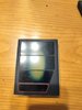
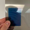
Example of GOOD 2nd polarization layer orientation (A very dark blueish-purplish color)
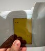
Example of BAD 2nd polarization layer orientation (Sort of a yellow color)
After correctly applying the polarization layers to both front and back you should have an LCD unit that looks like so-
(With the right lighting you should still be able to see the digits/icons.)
———————————————————————————
REASSEMBLY OF THE INSTRUMENT CLUSTER-
———————————————————————————
(Sorry for the lack of pictures here, I ran out of picture slots on the forum. Just refer to the top pictures in the reverse order, in conjunction with the below instructions.)
1. Place the LCD unit into the black metal bracket. (Larger piece of glass facing towards the front)
2. Put the white conductive rubber strips on either side of the back of the LCD unit.
3. Drop the white plastic LED diffuser into the black metal bracket. (It should fit perfectly with the white conductive rubber strips on the sides.)
4. Grab your main PCB (The one with the dials) from the safe place you put it.
5. Gently bend up the black dial cover (with all the tach and speedo numbers) and slide in the completed LCD assembly. (Careful not to scratch your main PCB or break off an LED with the 4 little metal flanges)
6. Once underneath the dial cover, with the little metal flanges poking through the main PCB. Carefully re-bend the metal flanges so that the LCD assembly is re-secured to the main PCB.
7. Drop the main PCB assembly into the rear housing.
8. Re-plug the 3 electrical connections for the idiot lights, headlight adjuster, and trip buttons.
9. Now grab the front instrument cluster housing from the safe place you put it. Be sure to clean the underside of the transparent plastic, then connect the front and back housings together.
10. Flip the entire assembly over and install all the screws.
(Don’t forget the 2 headlight adjuster screws!)
11. Flip the instrument cluster right side up, and pop the headlight adjuster knob back on its metal post.
You did it!
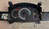
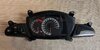
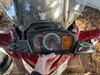
You should now have a completed (and beautiful) Instrument Cluster that looks like this-
Here's an easy way to test your instrument cluster without removing all the panels required to properly install it.-
Move your windscreen to the upper most position, then remove the 8x plastic pins on the front black fairing cowl and the 4 Philips screws in the dashboard just above the headlight adjuster and idiot lights.
(Those are also holding the front black fairing cowl on.)
Gently slide the cowl up and you will have easy access to the 2x instrument cluster wiring harness connectors.
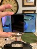
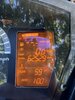
Plug in the instrument cluster that you're testing, and turn the bike on-
Quite the improvement if I don't say so myself...
Congratulations on saving $100-$200 and also preserving the limited supply of parts for the ST1300. I’m sure your bike, and the earth will thank you.
Now get on your bikes and ride!
Dedicated to Larry (IGOFAR) for helping me and many others with their ST1300s. I hope this guide is 1% as helpful as you are Larry.
———————————————————————————
This is an issue I’ve seen with MANY ST1300s online, as well as on my own 2 personal bikes. (Maybe you've seen or experienced this as well!) The LCDs have a tendency to get yellow sunspots if left out in the sunlight for seemingly ANY amount of time. Like many ST owners I have too much time on my hands, as well as a neurotic yearning for "perfection". This causes many of us to buy entirely new instrument clusters to remedy this small issue. As parts for these beautiful bikes become more and more scarce, this wasteful use of entire instrument clusters is going to come back to bite us. But with a bit of time (2-4 hours) and care, you can save yourself 100s of dollars and keep the CORRECT mileage for your bike. Also, frankly, I wasn’t satisfied with the videos and guides that I found online for this procedure.
It is for these reasons that I have created this guide. To as simply and as quickly as possible, repair rather than replace the LCD inside of the dashboard instrument cluster.
Now I warn you, this is a “mildly” dangerous procedure. But if taken slowly and with appropriate caution, I know you can do it!
(I’m an idiot and I did it successfully to both my ST1300s, as well as on my Aprilia Falco)
To keep this guide short-ish, I will not explain how to remove the instrument cluster dashboard from the Bike, as there are already many wonderful guides on the forum that will show you how to accomplish that.
LINK TO DASHBOARD REMOVAL GUIDE
———————————————————————————
REQUIRED TOOLS AND MATERIALS-
———————————————————————————
This particular guide will focus on taking the instrument cluster itself apart (as little as possible) to remove the LCD unit and repairing the sun damaged LCD display itself with a sheet of LCD polarizing film.
To complete this process you will need-
Sharp scissors
A Screwdriver with PH2 Phillips bit
(I prefer a 1/4in ratchet but that’s just me.)
Pliers (Needle nosed preferred, though I used regular pliers.)
Plastic pry tool
Razor blade with a razor blade holder
Rubbing alcohol (preferably 70% or higher)
Cloth (for rubbing alcohol)
And of course, LCD polarizing film - Here is a link to exactly what I bought on Amazon.
But most importantly for this endeavor, you will need PATIENCE.
———————————————————————————
DISSASEMBLY OF THE INSTRUMENT CLUSTER-
———————————————————————————
Like I said earlier, we will start with the instrument cluster out of the bike and on a table. (Using a tablecloth will help stop the screws from running away on you.)
Begin by using your plastic pry tool to pop off the headlight adjustment knob on the left side of the front of the unit. (Mine gave me a surprisingly hard time, so be careful not to break yours.)
Now flip the unit over and remove the 9x PH2 screws around the perimeter. (These will be the ones with the larger heads.)
Then remove the two smaller headed PH2 screws behind the headlight adjustment knob. (Place them with the adjuster knob so you know where and what they are.)
Carefully separate the front and back housings of the instrument cluster by pulling on the edges of the front housing.
(If you’re having too much trouble, you might’ve forgotten a screw!)
Front and back half successfully separated!
Set the front half of the unit in a safe place to the side.
Now remove the 12x smaller headed screws on the back half of the unit.
After removing those 12 screws, the speedometer and tachometer portion of the unit will drop out so be careful!
Flip the unit over and carefully unplugged the idiot lights, headlight adjuster, and trip buttons.
(All the other guides I’ve seen online have had you remove the screws to the idiot light, buttons and headlight adjuster PCBs but that’s just a waste of your time that incurs even more danger.)
Now, while holding the unit face up, place your left hand on the Speedo/tach dial cover, then with your right hand flip the entire unit over.
The main PCB should then fall out with no force required.
Set the main PCB down on its face.
(Again, remember to be gentle as the speedometer and tachometer stopper pins are INCREDIBLY easy to break.)
(Every other guide I’ve seen online will have you take off the speedo and tach needles, and remove the entire dial cover. Lucky for you this is an unnecessary step! Also, by not removing the needles, this keeps your speedometer and tachometer perfectly accurate.)
There are four metal flanges on the rear of the LCD unit that you need to bend straight so that they fit through the PCB. (This is where you use your pliers.)
Once you have bent all 4 metal flanges completely straight, gently push on the flanges until they are all flush with the PCB.
The front dial cover is flexible enough for you to slip the LCD unit out and to the right. (It’s flexible, but still breakable. Be careful.)
You should now have the LCD assembly separated from the main PCB and dial cover. Place the main PCB in a safe space off to the side.
Now with the LCD assembly separated, we can get a real good look at the damage.
Begin by removing the white plastic LED diffuser bracket on the back of the LCD assembly. It should lift away with no force.
Then proceed with removing the black metal bracket surrounding the LCD. Keep in mind that the LCD unit is glued on the edges to this metal bracket. So it will require SOME force.
(Just use your hands for this part, using tools to pry will only risk damage to the LCD unit.)
There are two white conductive rubber strips lightly glued to the back edges of the LCD unit. Your main PCB communicates with the LCD via these conductive rubber strips, so make sure to keep them clean. Gently peel these off and place them with the other parts.
You will now be holding just the LCD unit and the “melted/bad” polarized layers. Now this is where the razor blades and patience comes in.
(This is gentle reminder of how thin and fragile the part we are working with is.)
———————————————————————————
REMOVAL OF THE OLD POLARIZATION LAYERS-
———————————————————————————
You will now start peeling off the polarization layers on the front AND back of the LCD unit.
Before you begin, here are a few tips from my personal experience in order to save your day and LCD-
1. You will notice that there are two pieces of glass that make up the LCD unit. A slightly larger piece of glass (front glass) and a smaller piece (rear glass). Since the edges of the front glass are obscured by the black metal bracket, an accidental chip on the front glass is less dangerous than a chip on the rear glass. (Though chipping the front glass should still be avoided at all costs.)
2. The smaller piece of “glass” (on the back side) is the LCD display itself. (This is where you should take most of your care and time.)
3. When using your razor blade, be VERY careful when working around the EDGES, as even very little force with a razor blade can chip the LCD. For the safest results, it is best to use your razor blade, perpendicular to the edge you are working on.
4. If you do happen to make a small chip on the edge of the LCD, you MIGHT still be okay, depending on if the chip intrudes on the digits/icons. (Don’t ask me how I know...)
5. So long as you are not using a diamond tipped razor blade (If you are, where the hell did you get that?) the front glass and LCD WILL NOT be scratched by a steel razor blade.
(If you do see scratches, there is either another layer of polarization that you need to peel off, or there is still remaining old adhesive from the old polarization layers.)
6. With your razor blade peel up all four corners of the film, it really helps the layers to come off cleanly.
7. Wiggle the blade left to right rather than using brute force.
8. Don't cut towards yourself or your fingers.
———————————————————————————
Front polarization layer removed.
Back polarization layer removed.
With JUST your razor blades (and patience) you should be able to get the LCD unit as clear as in the image below. Also in the right lighting, you will still be able to see the digits and icons. (Neat!)
Give the LCD unit a quick wipe down with your isopropyl alcohol and cloth.
———————————————————————————
NEW POLARIZATION LAYERS APPLICATON-
———————————————————————————
The correct orientation of both polarization layers is incredibly important to the proper function of the LCD, so listen carefully. (If you have an LCD TV nearby, it’ll be useful right about...now.)
We will apply the rear polarization layer first. This is the layer on the back of the ACTUAL LCD (The smaller piece of glass).
Orient the polarization film so that in the vertical position it blocks light from your LCD TV. Like so-
Cut a piece of polarizer film that is slightly larger than the rear (smaller) piece of glass. This will allow you some wiggle room during the application of the polarization film to the glass. (I will tell you how to take care of the overhanging polarizer film in a moment)
Remember that any "under coverage" will be visible in the final product as a bright spot.
(Which you don’t want, unless you just really enjoy doing this for some reason...)
Before applying a polarization layer it’s a really good idea to wash your hands with soap. Also, with a piece of plastic or something create a little "roof" that your hands can work under, this can help stop dust from falling on the glass during the installation process and leaving air bubbles that are impossible to get out.
Clean the side of the LCD that you’re going to apply the film to while it’s facing down. (Again this is to prevent dust from falling on it before you install the film)
Quickly place the LCD unit under the "roof" (right side up now) then peel the #1 side of the polarizer film, and apply the film with haste AND precision.
Gently work out the air bubbles trapped underneath the polarizer film with your finger nail, THEN peel off the #2 "protective layer" from the polarizer film.
(This will help reduce scratches on the new film.)
Now to take care of the overhanging polarizer film, simply run your razor blade along the edges of the glass to trim the film perfectly to size. Don’t press too hard as it is very easy to chip the glass while running your razor blade along the edges.
At this point you should have the back side polarization filter applied cleanly, and it will look as such. (Rotate the LCD unit in front of your TV for some good clean fun.)
We will now apply the polarization film to the front part of the LCD unit (The slightly larger piece of glass). Again, orientation of the film is critical to function, so here are two examples, one good and one bad.
Example of GOOD 2nd polarization layer orientation (A very dark blueish-purplish color)
Example of BAD 2nd polarization layer orientation (Sort of a yellow color)
After correctly applying the polarization layers to both front and back you should have an LCD unit that looks like so-
(With the right lighting you should still be able to see the digits/icons.)
———————————————————————————
REASSEMBLY OF THE INSTRUMENT CLUSTER-
———————————————————————————
(Sorry for the lack of pictures here, I ran out of picture slots on the forum. Just refer to the top pictures in the reverse order, in conjunction with the below instructions.)
1. Place the LCD unit into the black metal bracket. (Larger piece of glass facing towards the front)
2. Put the white conductive rubber strips on either side of the back of the LCD unit.
3. Drop the white plastic LED diffuser into the black metal bracket. (It should fit perfectly with the white conductive rubber strips on the sides.)
4. Grab your main PCB (The one with the dials) from the safe place you put it.
5. Gently bend up the black dial cover (with all the tach and speedo numbers) and slide in the completed LCD assembly. (Careful not to scratch your main PCB or break off an LED with the 4 little metal flanges)
6. Once underneath the dial cover, with the little metal flanges poking through the main PCB. Carefully re-bend the metal flanges so that the LCD assembly is re-secured to the main PCB.
7. Drop the main PCB assembly into the rear housing.
8. Re-plug the 3 electrical connections for the idiot lights, headlight adjuster, and trip buttons.
9. Now grab the front instrument cluster housing from the safe place you put it. Be sure to clean the underside of the transparent plastic, then connect the front and back housings together.
10. Flip the entire assembly over and install all the screws.
(Don’t forget the 2 headlight adjuster screws!)
11. Flip the instrument cluster right side up, and pop the headlight adjuster knob back on its metal post.
You did it!
You should now have a completed (and beautiful) Instrument Cluster that looks like this-
Here's an easy way to test your instrument cluster without removing all the panels required to properly install it.-
Move your windscreen to the upper most position, then remove the 8x plastic pins on the front black fairing cowl and the 4 Philips screws in the dashboard just above the headlight adjuster and idiot lights.
(Those are also holding the front black fairing cowl on.)
Gently slide the cowl up and you will have easy access to the 2x instrument cluster wiring harness connectors.
Plug in the instrument cluster that you're testing, and turn the bike on-
Quite the improvement if I don't say so myself...
Congratulations on saving $100-$200 and also preserving the limited supply of parts for the ST1300. I’m sure your bike, and the earth will thank you.
Now get on your bikes and ride!
Dedicated to Larry (IGOFAR) for helping me and many others with their ST1300s. I hope this guide is 1% as helpful as you are Larry.
Last edited:
")