OP
OP
This is from my Service manual...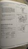

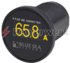
I put an ammeter on my GL1000. I don't remember where I got it but it was very close to the orange gauges of the VF1000 Interceptor I got years later.The best way to do that would be with an ammeter, but you would have to modify the wiring at the battery to read current in both (charging and discharging) directions with a single meter.

Just to mention it, an ammeter is actually a voltmeter calibrated to read the voltage across a low-value, high-wattage resistor that must be inserted in the wire that carries the current (exc. starter) into and out of the battery.Powerwerx also has Ammeters.
Would the same problem you mention exist with the ST1300? So you would need two separate sensors/shunts, that you could possibly switch back and forth to the meter?Just to mention it, an ammeter is actually a voltmeter calibrated to read the voltage across a low-value, high-wattage resistor that must be inserted in the wire that carries the current (exc. starter) into and out of the battery.
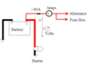
The problem with wiring one in the ST1100 is that the charging current and the bike's running current have different electrical pathways between the alternator and the battery, and between the battery and the main fuse.
I'd have to see a 1300 diagram to answer you, but it would most likely be easier to relocate either the alternator feed connection or the main power wire(s) connection. Look at this generic diagram I found on the webs.Would the same problem you mention exist with the ST1300? So you would need two separate sensors/shunts, that you could possibly switch back and forth to the meter?
It would take more effort to install an Ammeter because depending on the maximum current flow measured, the meter has to be installed in Series (in line) with the current being measured. Depending on the current flow, I may have to install a load in parallel with the meter to divide the current to allow to measured amount of current to flow across the meter. At that point, I may be introducing errors in the meter reading due to the amount of current the meter is reading, then you have to adjust for current ratios between the load current and the measured current (unless you are fortunate enough to have a meter that is calibrated for the parallel load in the circuit. Better for me to install a voltmeter which a large impedance to allow a much smaller current flow, and therefore less current drain on the Charging circuit. Thx all for your input so far. I have much food for thought. Another option for me to consider is an Ammeter that measures current using induction.Just to mention it, an ammeter is actually a voltmeter calibrated to read the voltage across a low-value, high-wattage resistor that must be inserted in the wire that carries the current (exc. starter) into and out of the battery.
The problem with wiring one in the ST1100 is that the charging current and the bike's running current have different electrical pathways between the alternator and the battery, and between the battery and the main fuse.
")
Larry:ust to mention it, an ammeter is actually a voltmeter calibrated to read the voltage across a low-value, high-wattage resistor that must be inserted in the wire that carries the current (exc. starter) into and out of the battery.
That means it would have to carry starting current, too. Electronic ammeters tell you to use the negative wire so the electronics inside can use the same negative reference, simplifying the circuit.It came with a shunt that needs to be installed in series with the negative battery cable.
The meter and shunt are designed as a calibrated set. The meter is designed to display current as its measuring voltage drop, and the resistor's power rating determines its maximum current capacity.Do they calibrate the ammeter to work with the natural resistance that is inherent in that length/size piece of steel that they supply as a shunt?
Or, was that shunt manufactured with additional resistance embedded inside of it somehow to calibrate it to the ammeter?
Correct. It is an engine analyzer intended to diagnose starter and charging systems on 12V vehicles.That means it would have to carry starting current, too.
This shunt in only maybe 3/16" thick, but it is not just a piece of steel? It has resistors of specific values built in to it somehow?The meter and shunt are designed as a calibrated set. The meter is designed to display current as its measuring voltage drop, and the resistor's power rating determines its maximum current capacity.
No, the block of metal itself is the resistor. It's a very low resistance, a small fraction of an ohm, and it's large so it won't get warm while dropping the small fraction of a volt that the meter is reading.This shunt in only maybe 3/16" thick, but it is not just a piece of steel? It has resistors of specific values built in to it somehow?
Nothing is visible from the outside except flat chrome looking steel plate.
Another type of meter I have worked with is the "inductive" type ammeter, which expanded on the D'Arsonval meter movement (on which all analog meter movement is based on). in that case the meter coil itself was used as a load. Contrary to popular belief, there is resistance in a conductive wire that is based on the type of material the wire is made from, as well as the diameter of the conductive material. As part of my naval "A" school training, I had to learn and memorize some "ugly" formulas regarding the interactions of conductive materials and the effects on signal output/sensitivity during my radio and RADAR studies. (flashbacksThat means it would have to carry starting current, too. Electronic ammeters tell you to use the negative wire so the electronics inside can use the same negative reference, simplifying the circuit.
The meter and shunt are designed as a calibrated set. The meter is designed to display current as its measuring voltage drop, and the resistor's power rating determines its maximum current capacity.
The same meter with a shunt of the same resistance, but of a lower power rating, would read the same current, up until the point where the resistor overheated.
). All of this is pretty much moot for me as I plan to install a Voltmeter instead of an ammeter.Good, thanks.No, the block of metal itself is the resistor.