Injectors not getting power

Joined
Sep 6, 2024
Messages
9
Age
65
Location
oregon
Bike
ST1300
I'm new here, so bear with me if I sound like a moron. I couldn't find anything on point in my search with similar issue.

got my ride used, a 2010 ST1300 with 65,000 miles. I've replaced many of the usual suspects, SMC, Thermostat, brake slave, etc. as well as the fuel pump a couple weeks ago. Today I pulled the tank and removed the injectors, had them cleaned plus replaced the filters and cleaned the rails and such.

I reinstalled everything and now the injectors have no power. Spark to the plugs. power to everything else, no F1 light, removed the line from the pump and it is pushing strong, but the injectors have no power.

I saw no fuses were bad, but I could have missed something. Is there a go to location to check for this?

Thanks in advance for the consideration

Marty
 
Welcome @justmarty

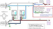
From the circuit diagram that I am looking at the one for 2008 models onwards posted by SpikingJC here Post#3 . - This is one of the few that shows the multiway connectors behind the headlamp.

It shows that the power for the injectors comes from the same connector that feeds the ignition coils, FI and Fuel pump. The power source is turned on by the bank angle sensor relay - which requires two 'switches' to be turned on before it switches on the relay - the bank angle sensor and the run/stop switch. (Plus the ignition of course).

If you are getting power to the fuel pump OK then the same circuit should turn on the fuel injectors. If not:

Check that you have 12v ish to the black/white lead going to the injectors.
Check that the other lead to the injectors is sound. Don't probe it for resistance - it is connected to the ECU.
Check your fuel pump connection hasn't been by-passed. Pull the fuse for the fuel pump to make sure that it doesn't work when the fuse has been pulled, but it does work when it is replaced.
Do the same with the fuse for the bank angle sensor.
(both of the above should prevent the fuel pump relay from operating, so the pump will not work. If the pump does work then the previous owner has 'cured' a problem by pwereing it from somewhere else.

There are two multiway connectors - according to the diagram one is yellow, one is purple. These are buried behind the headlights. One is for the b/w leads which supply power. The other is for the various earths. Check that these look sound - some report the plastic melting and corrosion of terminals.

Not that the fuel pump will operate only for a second or two after switching on the ignition and then it turns off. Sometimes if you have done this a number of times, the the fuel pump doesn't operate at all for a while.

The link below is related in that the power for the injectors and the power for the fule pump are truned on by the same relay - the bank angle sensor relay.


That is as much help as I can offer on this subject, I'm afraid. I'll let someone else chip in
Your awesome, TYVM. Am anxious to get on this tomorrow.
 
Ooop! That line should have read .....

Note that the fuel pump will operate only for a second or two after switching on the ignition

Also - I meant to say...... I have never seen mention of a purple / pink connector in anyone's posts - only on this circuit diagram. Only yellow. I've never gone hunting for it on my bike either, although I've seen the yellow one. Didn't spot a pink one.

Whatever colour it is , you can verify whether it is the earth connector or the power connector by checking the colour of the leads going into it. Green = earth, Black/white = Power. Note that the diagram shows that the power connector shows three separate groups of wires that are connected. The earth connector links all of the earth wires together.
OK, so I finally, after 2 days testing everything and beating my head against the wall, I have come to the conclusion that the ECU is bad. I found the red wire from what I believe originates at the ignition switch as it connects to the starter motor/clinoid, the unit up near the main fuse and battery, is heavily blackened from overload.

When I first got the bike my 4 year old took the keys out and got them stuck in the ignition. Had to trailer it to the mechanics to get it out and the ignition switch has been an issue ever since.

So the question I have is can the ecu be repaired that you know of? appreciate the time you gave me already. thanks
 
I know that people have had the HISS version programmed to match a chipped key - but that is for European bikes. But programming a working unit is rather different from repairing a damaged one.

Its odd for the Ecu to be damaged by heavy current. No heavy duty wires go near it, the ECU switches on relays and lets them carry the heavy loads . Often, as is the case with the fuel pump circuit, the ECU controls the circuit by completing the circuit to earth for the relay trigger coils.

So just cos you have signs of overloading at the red wire ignition switch, I don't think it means that the ECU has been subjected to that amount of current. There may be other reasons.

When you say that the injectors have no power, have you traced the circuit diagram and tested for the presence of 12v at each point from the fuse into switches and out of switches / into relays and out of relays to determine where the circuit is broken ? Where does the circuit stop showing Voltage ?

Did you download the pdf file about the fuel pump circuit that I posted ?

In there I describe where you can probe the relay terminals and give diagrams and photos.

I'll give a for instance. Do you know if power is getting to (say) the fuel pump relay. If the answer is yes it is, then you have some power and any fault lies after that. If the answer is no it isn't, then you need to find what comes before that in the circuit diagram and see if power is getting to there.

Thats just an example. The same sort of thing applies to lights, Abs.

I've no experience with faulty ECUs or ignition switches. I do know the switch carries some serious current and often switches on the main feed to the fuse box. The fuses would be a good place to start - remove the fuses (take photos first) use your meter to find out which ones are getting power and which aren't. Go from there.

Can you read a circuit diagram ?
Do you know how a relay works ?
Do you know how to use a multimeter to measure voltage and/or resistance?

Have you checked your side stand switch, neutral switch and clutch switch ? The bike is going to remain dead if these don't send the right signals to the ecu. That is because the ECU does not turn on the required relays unless it is safe to start the engine.

The solenoid black / melted wire is a common problem if owners add accessories simply by tapping into existing circuits. There is some spare capacity on a couple of the circuits, but not for adding many things like auxiliary lights, superloud horns, heated jacket power. The multi-way power connector and the multiway earth connector up near the headstock behind the headlight cowl also suffer in this scenario.

Even if the ECU has gone south, you need to get these issues sorted first, and try to find out what caused them - start by disconnecting any add on accessories, then check main connectors for signs of corrosion. Find the main earth connections, undo them, clean up the frame, bolt and connection terminal. Bolt it up bare metal to bare metal and protect it with grease or brush lightly with ACF50 to stop it corroding again. You're supposed to use dilectric grease. Sometimes corrosion spreads up the wires. The core becomes blackened instead of shiny. In extreme cases such wire may need to be replaced.

If going down the ECU route, you might be lucky at breaker's yards or ebay. The dealers that know what they are doing may well be selling keys, ignition switch, and filler caps as a bundle - and in Europe because of HISS they will include the ECU). These are more likely to have come from a crashed bike rather than one that has stopped working. Breakers have no way of knowing whether an ECU is working or faulty, so they should be prepared to refund. You have to make sure that the product number is the same as yours. Private individuals may simply be braking a bike for parts because they cannot get it to run.
 
Last edited:
I know that people have had the HISS version programmed to match a chipped key - but that is for European bikes. But programming a working unit is rather different from repairing a damaged one.

Its odd for the Ecu to be damaged by heavy current. No heavy duty wires go near it, the ECU switches on relays and lets them carry the heavy loads . Often, as is the case with the fuel pump circuit, the ECU controls the circuit by completing the circuit to earth for the relay trigger coils.

So just cos you have signs of overloading at the red wire ignition switch, I don't think it means that the ECU has been subjected to that amount of current. There may be other reasons.

When you say that the injectors have no power, have you traced the circuit diagram and tested for the presence of 12v at each point from the fuse into switches and out of switches / into relays and out of relays to determine where the circuit is broken ? Where does the circuit stop showing Voltage ?

Did you download the pdf file about the fuel pump circuit that I posted ?

In there I describe where you can probe the relay terminals and give diagrams and photos.

I'll give a for instance. Do you know if power is getting to (say) the fuel pump relay. If the answer is yes it is, then you have some power and any fault lies after that. If the answer is no it isn't, then you need to find what comes before that in the circuit diagram and see if power is getting to there.

Thats just an example. The same sort of thing applies to lights, Abs.

I've no experience with faulty ECUs or ignition switches. I do know the switch carries some serious current and often switches on the main feed to the fuse box. The fuses would be a good place to start - remove the fuses (take photos first) use your meter to find out which ones are getting power and which aren't. Go from there.

Can you read a circuit diagram ?
Do you know how a relay works ?
Do you know how to use a multimeter to measure voltage and/or resistance?

Have you checked your side stand switch, neutral switch and clutch switch ? The bike is going to remain dead if these don't send the right signals to the ecu. That is because the ECU does not turn on the required relays unless it is safe to start the engine.

The solenoid black / melted wire is a common problem if owners add accessories simply by tapping into existing circuits. There is some spare capacity on a couple of the circuits, but not for adding many things like auxiliary lights, superloud horns, heated jacket power. The multi-way power connector and the multiway earth connector up near the headstock behind the headlight cowl also suffer in this scenario.

Even if the ECU has gone south, you need to get these issues sorted first, and try to find out what caused them - start by disconnecting any add on accessories, then check main connectors for signs of corrosion. Find the main earth connections, undo them, clean up the frame, bolt and connection terminal. Bolt it up bare metal to bare metal and protect it with grease or brush lightly with ACF50 to stop it corroding again. You're supposed to use dilectric grease. Sometimes corrosion spreads up the wires. The core becomes blackened instead of shiny. In extreme cases such wire may need to be replaced.

If going down the ECU route, you might be lucky at breaker's yards or ebay. The dealers that know what they are doing may well be selling keys, ignition switch, and filler caps as a bundle - and in Europe because of HISS they will include the ECU). These are more likely to have come from a crashed bike rather than one that has stopped working. Breakers have no way of knowing whether an ECU is working or faulty, so they should be prepared to refund. You have to make sure that the product number is the same as yours. Private individuals may simply be braking a bike for parts because they cannot get it to run.
I pulled the alarm, the phone holder with USB port, the rear taillight flasher, the auxiliary cig lighter that was mounted in the right side diddy box, and the heater cable ports that were on the side and near the steering head.

The reason I was drawn to the ignition switch and the ECU is that I had power to the spark plugs/coil and none to the injectors. Then as I turned the bike on and off testing connections and removing accessories I had power to the injectors and none to the plugs/coil.

It costs $50.00 for an outfit to review the computer. And I'll go back and double check the relays/fuses/connectors/ground connections one more time to see if I find something different.

Thanks Again, I'll keep you posted
 
The power to the coils and to the injectors is provided through the black/white leads. These are all connected together by one of the multiway connectors. Ask the question. If they are not all showing 12v ish and they should all be connected together, why is that ?

If the power to the coils and to the injectors on the black/white leads is not consistent, then there is a problem with that multiway connector or the power supply to that connector.

The power comes from fuse L - FI injection coil / Fuel pump. It is switched on / off by the Bank angle sensor relay. The relay is turned on by power from the bank angle sensor and the stop switch. Details of that are in the diagram that I linked to earlier with a lot of examples of how to test it. I'll link it here too.


1727475079381.jpeg
just went out this afternoon and now I don't have any power to the fuel pump. So I put the voltage tester down, mixed an adult beverage and will try again tomorrow.

Thnx for your timely reply
 
just went out this afternoon and now I don't have any power to the fuel pump. So I put the voltage tester down, mixed an adult beverage and will try again tomorrow.

Thnx for your timely reply
Since you had the injectors out it might be worth your while to check the wiring and all of the connectors/connections for the wiring and the injectors. If the ECM detects any fault with any of the injectors it disables the fuel pump and will not re-energize it until the fault is no longer present. Depending on what the fault with the injector(s) is it will not necessarily register a fault code.
 
Since you had the injectors out it might be worth your while to check the wiring and all of the connectors/connections for the wiring and the injectors. If the ECM detects any fault with any of the injectors it disables the fuel pump and will not re-energize it until the fault is no longer present. Depending on what the fault with the injector(s) is it will not necessarily register a fault code.
It was weird as I had NO POWER (capital letters to add emphasis that although I'm married with kids, I'm not totally dumb) to the injectors and the fuel pump fired up every time I turned on the bike. Now there is power to the injectors and the fuel pump is without power.
 
I forgot to add in my essay about the black and white wires. Once all relays are turned on, and power is getting to the fuel pump, injectors and coils then the b/w wires are always live according to the circuit diagram. I said that.

What I forgot to say was that the completion of the circuit to turn for each device is through the ECU - which turns on/off the connection to earth.

If the ecu has turned on the connection to earth, then that voltage reading will drop. (at the relay and at the other coloured wire, that will be zero when the Ecu has turned on the circuit. When the circuit is not turned on by the ecu, YOU are completing the circuit through the volt meter by probing the coloured wire so you will get some voltage but not 12v. To check voltage it is best to check at the disconnected connector.
 
Last edited:
I forgot to add in my essay about the black and white wires. Once all relays are turned on, and power is getting to the fuel pump, injectors and coils then the b/w wires are always live according to the circuit diagram. I said that.

What I forgot to say was that the completion of the circuit to turn for each device is through the ECU - which turns on/off the connection to earth.

If the ecu has turned on the connection to earth, then that voltage reading will drop. (at the relay and at the other coloured wire, that will be zero when the Ecu has turned on the circuit. When the circuit is not turned on by the ecu, YOU are completing the circuit through the volt meter by probing the coloured wire so you will get some voltage but not 12v. To check voltage it is best to check at the disconnected connector.
OK.

So I found a 20/8/17 reply you posted detailing the load to everything.

I looked at my relay connectors and cannot find the same colors on them that you outline, but maybe the following helps you, help me, diagnose the issue. Within a couple of days after buying the bike my son messed up the ignition, as I already mentioned. After getting it back I realized/discovered? (it may have always been this way) that the kill switch did not shut down the bike, but if in the off position the bike wouldn't start.

One of the 2 leads has constant power right now.

As to the Bank Angle Sensor, it has 3 leads and both the red and B/W have 12 volts. Your 2017 article says that the red should only be at 1.

Honestly I considered myself fairly mechanically inclined before this, but I realize my head is spinning reading these diagrams and figuring out which is what. All the relays were in a mess, just shoved into the relay covey so I'm double lost as to what is what except for the flasher relay.

Anyway, I'm going to take a nap with my daughter to hopefully lose this headache and if you have any ideas, please let me know
 
Hi


0. I don't recall whether you have investigated the two multiway connectors - Black/White leads in a yellow connector. Prone to meltings / corrosion - in which case it will knock out apparently random power to fule injector, fuel pump, coils etc. It is the main power feed for all of these devices.

And the Pink (?) multiway connector which does the same thing for the green earth leads, and separately for the green/orange leads.

1. I don't know which 2017 article you are referring to. I cant find one of mine for 20 Aug 17.

2. The diagram that I posted comes from an article that I wrote - linked in the same post. You need to download that article and understand what is going on - I've attached it to this post to save hunting it down. The diagram is actually three separate circuits - each of which is described and explained in some detail, (with the irrelevant parts greyed out). In that article I explain that the Bank Angle Sensor is NOT a switch, but that I have represented it as a switch because it turns on or off the Bank Angle Relay. It is actually an electronic device which when 'on' provides enough of a current flow to the coil in the bank angle relay to turn the relay on.

3. You will have a problem if you cannot identify the relays if they have been put back in the wrong positions. That may need to be your first job. I need a diagram to help - hang in, I'll get to my Pc. I'll be back in a tick........

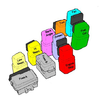
Relay diagram taken from the UK service manual and coloured in. Shown in the relative positions behind the left hand side cover.
1727556572876.png 1727556792547.png

Both of these digrams come from this link here - post number 4. - but it is attached to this post now as well. Ignore the bit outlined in red on the headlight diagram, that is for the 'flash to pass' switch which doesn't exist on USA bikes.

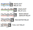
Here are the documented colour codes for most of those relays. Not that Bl = Black, Bu = Blue, P= Pink, R/O = Red/Orange.
1727561030005.png

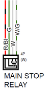
The main stop relay and Bank Angle Sensor connector

1727560964489.png1727561244209.png
The Main Stop Relay is triggered by the Red/Black wire which comes direct from the ignition switch. It feeds the horn and the brake stop light. So if you disconnect that, the brake light and the horn will not work. I don't know if this is the same as the engine stop relay. There are two Main Stop relays on the circuit diagram. I'll come back to this.

The Bank Angle Sensor connector. Green is earth. W/Bl comes from the Starter/Bank Angle Sensor Fuse D which is truned on with the ignition switch. Red/Orange or Red /White will have a small 0-1v voltage on it when the bike is upright - so enough to put at least an 11 volt difference through the Bank Angle Relay trigger coil. So it acts like a switch in effect - but the voltmeter gives a confusing pictures.


The plug in relays are mostly the same kind. Low Beam, High Beam, Bank Angle Sensor, Fuel Cut, Fan and Main Stop Relay.

You can easily identify the headlight relays. Both of them affect only the left hand headlight. (Big assumption that the USA model is wired the same as the UK model). Whatever - you will feel them clicking if you you switch from low to high beam. Remove both of them and you will find that only the right hand headlight will be on when you switch between low and hight beam.

Before removing more than one relay, make sure that the connector is identified in some way. I use coloured cable ties and write down what each colour means. Or tape on a label around the wires that you can keep in place. When you put the relays back, do one at a time and label the top of the rubber holder in some way.

Screen is also easy to identify in the same way.

All I can do to help with the others is to identify the realys by the wire colours. One of the pages in the attached document describes which terminals are the coil / trigger connectors and which are the switched power connectors - so explanations like this.

1727559573176.png

I am assuming that your bike has ABS. IT makes a difference to the circut diagrams if it isn't

So - from @SpikingJC's posted circuit diagram:
 

Attachments

  • ST1300 - Fuel Pump Circuit - Answers on Back Page (3).pdf
    1 MB · Views: 0
Last edited:
Hi

I dont have much time today / tomorrow. Just quick comments.

1. I don't know which 2017 article you are referring to. I cant find one of mine for 20 Aug 17.

2. The diagram that I posted comes from an article that I wrote - linked in the same post. You need to download that article and understand what is going on. The diagram is actually three separate circuits - each of which is described and explained in some detail, (with the irrelevant parts greyed out). In that article I explain that the Bank Angle Sensor is NOT a switch, but that I have represented it as a switch because it turns on or off the Bank Angle Relay. It is actually an electronic device which when 'on' provides enough of a current flow to the coil in the bank angle relay to turn the relay on.

3. You will have a problem if you cannot identify the relays if they have been put back in the wrong positions. That may need to be your first job. I need a diagram to help - hang in, I'll get to my Pc. I'll be back in a tick........

Relay diagram taken from the UK service manual and coloured in. Shown in the relative positions behind the left hand side cover.

1727556572876.png
Here is the article I referred to

Please excuse the lengthy reply with no diagrams. I have been working through the wiring diagrams getting a grip on what feeds what, and trying to understand the electrical logic behind the Bank Angle Sensor, to make the diagram make sense. But read the bottom bit first - a useful link that I came across. It sounds familiar !!

Anna's Dad's Excellent wiring schematic is linked from Post #1 here.

So this is a sequence starting with the Bank Angle Sensor and checking that power is getting to each point in turn and that leads are intact to that point. You could jump in part way through I suppose, and find a switch relay that is working and move from there. Writing it this way makes it easier to cover all bases.

So I have assumed that the ignition switch is working, that power is getting through the main start relay and that power is getting to the fuses in the fuse box.

Briefly, the bank angle sensor provides a trigger for the bank angle sensor relay. The bank angle sensor relay provides power for the coils and injectors and to fuel cutoff relay (via the Run/Stop switch). The fuel cut off relay activates the fuel pump.
I would guess that with no power to coils or to the pump, the fault has to be the leads, switches and relays up to and including the Bank Angle Senor Relay.


The Bank Angle Sensor has 3 wires.

Black / White - which provides 12v when ignition is on. This comes from the 10A Fuse D in the forward fuse box and is not affected by the Red Runs / Stop switch.
Green which is connected to the chasis earth.
Red / Orange is presumably a signal wire to the bank angle sensor relay and should produce 0-1 volt in the upright position when tested against the green wire (earth)

If the black / white lead gives the +12v reading and the red orange lead doesn't give 0-1v reading then the bank angle sensor must be suspect. The manual doesn't give a reading for when the bank angle sensor is tilted - it just says that the bank angle sensor relay should click. I suspect it would show an open circuit - but I do not know. I also suspect, but I haven't tried this, that the bank angle sensor is providing a return to earth for the relay to be activated. The 0-1v reading is due to the electronic circuitry in the sensor.


The Run / Stop switch
has a couple of wires of note.

A black / white lead which provides the same +12v battery voltage from fuse D that supplies the Bank Angle Sensor. Test it against a good earthing point. There is no earth lead in the switch assmebly.

A black lead which shows battery voltage (12v) when the switch is on, and takes the +12v to the Bank Angle Sensor Relay. Again, test it against a good earth, with the switch turned on. If power isn't getting to the black/white lead, then there is a problem with the lead or connectors from the fusebox. If power is getting through, but power doesn't appear at the black lead at the switch, then there is a problem with the switch - or the short lead from the switch to wherever you take the reading.
Note that internally, the switch that powers the black lead, also provides power to the engine starter switch.


The Bank Angle Sensor Relay has 4 wires.

Like all basic relays, it has two wires which control the position of the switch (on/off), and two wires which provide the power in and the power out.

Assuming the previous items tested out OK: The Red/ Orange lead is the one from the Bank Angle Sensor and should display the same 0-1 volt reading when tested against earth. If it doesn't then the red/orange lead, or its connectors at either end must be suspect. I think that this R/O lead is the return to 'earth' lead via the Bank Angle sensor.

The Black lead is the battery voltage +12v power that comes from the Run / Stop switch. Test against earth, not against the Red / Orange lead - the Bank Angle Sensor has electronics which may not respond if the probes are put on the wrong way round. (My supposition).

Another test: Hold the relay in your hand and turn on the ignition and set the Run/Stop switch to Run. You should feel the click as the relay activates.

The Black / Pink lead is the source of the battery voltage from the 20A Fuse 'L' in the rearward fuse box. It should read 12v (ish) when measured against a good earth point. If it doesn't, check out the fuse and test the cable from the fusebox to the Bank Angle Sensor Relay for continuity (ie zero resistance).

The black/white lead from the relay is the battery voltage out of the relay to the next point int he circuit. It should read +12v (ish) when measured against earth when the relay has been activated. (ie when ignition is turned on - if the bank angle sensor is upright AND the Run/Stop switch is set to 'Run'. Check the voltage against a good earth. This black/white lead provides the 12v battery voltage to various devices from this point, including various sensors, the fuel injectors and the ECM. It also provides the voltage for the next stage - the Fuel Cut-off relay.

The Fuel Cut-Off Relay

I have 2 circuit diagrams and the one in my 2004 Honda Workshop manual differs at this point from the superior colour version 'R' that Anna'sDad has produced. If you haven't got it, then download it - it is worth its weight in gold. I'm going with Anna's Dad's version - I trust it to be more accurate for the 2009 model ST1300ABS.

A spur of the Black/White lead that comes from the Bank Angle Sensor feeds into the Fuel cut-off relay, and is connected to both the trigger and the input voltage contacts. Check that the battery voltage is reaching this point - tested against a good earth. You could also check that the same lead is supplying a voltage to the ignition coils (and to the fuel injectors). There are other sensors too which can be gleaned from the circuit diagram.

The other trigger wire at the Fuel Cut-off relay goes to the ECM - presumably enabling / disabling the return of the trigger voltage to earth. That is the Brown/Black wire. I would be wary of putting an ohmeter on this - I don't know what the voltage that is put out by the meter might do to the electronics in the ECM.

The Brown wire is turned on only if the relay has been activated by all of the other switches / relays described above being 'switched on'. If power is reaching this point, then the next stop is the fuel pump.

The Fuel Pump.

Has 3 wires. A Green wire which is connected to earth. The Brown wire provides the +12v batter voltage from the Fuel cut-off relay. Test the earth wire for continuity with a good earthing point, or the negative batter terminal. (0 Ohms). Test the brown wire for battery voltage against a good earth (+12v ish). Any fault here must be related to wiring or connectors. The other lead is for the reserve tank sensor.

If everything tests out, then the fuel pump should whirr into life. If it doesn't, you have missed something.

Ignition coils.

Low tension voltage (battery voltage) comes from the black and white leads already mentioned. The Blue/Yellow and Yellow/Blue leads (check the colours on the coils 2P connectors) feed straight to the ECM. All you can do is test for continuity (ohmeter) between the multi-pin connector and the coil.

Fuel Injectors.

Ditto the above. Check the colours of the wires feeding each injector (other than the black/white 12v lead) and find the same colours at the multiway connector that plugs into the ECM and check for continuity.

Finally - while checking things out for you I came across this on the forum:

https://www.st-owners.com/forums/showthread.php?97758-ST1300-Brains-required-for-non-starter/page3

It sounds like a very similar problem - and the fault turned out to be a corroded wire which feeds the fuse box - allowing a reading of 12v, but not allowing sufficient current to power anything ! I would guess that someone at some time had put one of those quick wire connectors onto the 12v feed. They slice through the outer protection and the blade contacts the inner core - leaving them open to the elements.

Last edited: Aug 23, 2017
 
Ah - Ok thanks. I got about half way through reading that thinking - "that's an interesting article you have found ... I've not seen this before". Before I realised that I had written it. 7 years is a long time.
 
Back
Top Bottom