Turn Signal Not Functioning

Joined
Dec 26, 2007
Messages
92
Age
76
Location
Fort Myers FL & Elkhorn WI
Bike
2007 ST1300
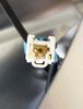
My right front turn signal isn’t working. The running light works but when I switch on the turn signal, the front light goes out completely. The right rear turn signal and indicator on the gauge panel flash rapidly. They flash normally for left turns. The left turn signal works properly. I tried replacing the right front bulb but that’s not it, the bulb is good.

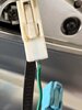
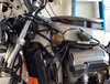
This problem came up after I replaced my engine sub-wire harness, thermostat, and most all the coolant hoses so I had the bike torn down quite a bit. The engine bay was a mess, so I did a lot of cleaning. There is a large connector on the left side of the bike frame just in front of the ignition coil and cylinder head. That was covered in grime so I cleaned that as gently as I could but I’m wondering if the turn signal wiring runs through there?

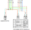
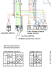
I’ve studied the wiring diagram, but the turn signal switch confuses me (diagram attached). I see the orange and light blue wires going into the switch, but those wires don’t appear to be switched so I’m guessing that is the running light connection. I see the orange/white and light blue/white wires going into the switch and that looks like what’s switched but the symbols are PO, PL, and PR. What does that stand for?

I’d be grateful if someone could explain what the Turn Signal Switch Continuity diagram shows.

Which wire should I be focusing on for the non-operational right turn signal? Anything else I should check?
 

Attachments

Joined
Aug 21, 2018
Messages
6,752
Location
Richmond, VA
Bike
'01 & '96 ST1100s
STOC #
9007
The orange and light-blue wires with the white stripe are the running-light wires.

The orange and light-blue wires without the white stripe are the turn-light wires.

The switch turns off each running light so that side flashes with greater contrast.

It still sounds like the right-front bulb is bad; test by swapping with the left bulb.

If it's not the bulb, then it's the wire feeding it, somewhere after the turn switch.
 
Last edited:
Joined
Sep 4, 2013
Messages
8,168
Location
Cleveland
Bike
2010 ST1300
The turn signal wires do run through the harness on the left side of the bike. That's where STS suggested inserting their auto turn signal cancelling gadget. i'd suggest you double check those big wiring connectors.
 

Obo

Joined
Oct 22, 2019
Messages
4,286
Location
East Coast Canada
Bike
'03 ST1300A
Check for power at the turn signal connectors at the mirror. The rear flashing fast means power is getting from the switch, to the flasher and out back. It's just not getting out front.

Hopefully the connector at the mirror is just bad, but if you don't have a good ground or power there then look at the connectors for the wiring harness you pulled apart.
 
Joined
Mar 20, 2016
Messages
1,209
Location
Auckland, New Zealand
Bike
2005 ST1300
STOC #
8901
I'm with Obo on this one; if you had the front fairing off then you had to remove the mirrors and the turn signal connectors. I had a problem with one of my connectors where the connector pin had backed out of the plastic plug body and had to be re-inserted after I bent the retaining tang out a bit.
 

Igofar

Site Supporter
Joined
Jan 8, 2011
Messages
7,128
Location
Arizona
Bike
2023 Honda CT125A
In days of old, when a Honda turn signal bulb went out, it caused the other lights to blink quickly.
Sounds like a bulb.
I’d start there
 
Joined
Aug 21, 2018
Messages
6,752
Location
Richmond, VA
Bike
'01 & '96 ST1100s
STOC #
9007
There are two types of thermal flashers. Both use a heating element and a bi-metallic-strip-activated switch contact. You can tell which you have by how it reacts when a bulb goes bad or otherwise goes out.

One type has the heater in series with a normally-closed contact; the heat caused by the bulb current opens the contact, the element cools, closes, and repeats. These stop flashing when a bulb burns out.

The other has the heater in parallel with a normally-open contact; the heat closes the contact, the element cools, opens, and repeats. These flash faster with only one bulb, but can handle more than two.
 
Last edited:

jfheath

John Heath
Site Supporter
Joined
Mar 18, 2006
Messages
2,858
Age
70
Location
Ilkley, W Yorkshire, UK
Bike
2013 ST1300 A9
2024 Miles
000679
STOC #
2570
What @Larry Fine said.

To answer the switch question.

Perhaps if I presented the diagram a bit more clearly - move things about and cut out the unwanted stuff.

There are four switches shown in the original circuit diagram Two of them of interest. These are shown below with the electrical continuity table positioned below the relevant switch. The Horn and the Dimmer switches, I have removed.

1683097738534.png

It looks like the USA turn button has two channels ie it is two electrical switches operated by the same mechanical switch. Our Uk bikes don't have the running lights in the lens, so our switch is different.

The Left switch is showing the connections for the turn signal itself in Right, Netral and Left posittions.
The terminals are labelled W for the switched power and R & L terminals.

The right switch - which is part of the same turn signal button - but which is isolated electrically - I think is providing the power for the running light so the the left light is on when the right indicator is flashing. When in the central position, both lights are on. These are terminals are labelled PO, PR, and PL

So for example when the turn signal button is set to the right turn position, the top row shows that:
W and R are connected - ie the Gr and the Lb wires - the right hand indicator.

and also

PO and PL are connected - The Bl/Br and the O/W wires - the left hand running light. The right hand running light is off.

If your running lights are working as expected, then you can ignore the PO PL PR terminals.

The Hazzard switch simply puts power into both left and right indicator circuits, and doesn't seem to care much about the running lights.
 
Last edited:
OP
OP
Ron_WI
Joined
Dec 26, 2007
Messages
92
Age
76
Location
Fort Myers FL & Elkhorn WI
Bike
2007 ST1300
Well, thanks to everyone for all the help, especially John Heath with the diagram explanation. It turned out to be an issue with the ground connector on the right side. I had looked at it when I changed out the bulb and thought it didn't look right but I couldn't push the metal into the plastic body any further. This time I compared it to the ground connector on the working left side and realized this was the problem. I pulled the connector out and cleaned up the plastic piece to get the dirt out. When I tried to put the connector back in, the same thing, it wouldn't go in all the way. So I turned it around and by gosh it fit in perfectly. I'm at a loss for how that could have gotten turned the way it was but my signal is working again.
 

Attachments

OP
OP
Ron_WI
Joined
Dec 26, 2007
Messages
92
Age
76
Location
Fort Myers FL & Elkhorn WI
Bike
2007 ST1300
John Heath, thanks again for explaining the diagram. What was throwing me on the manual diagram was the section showing the wires coming into the switch. The orange and light blue wires for the blinker went to a connection that wasn't represented as a switch as it is in the diagram you show. The orange/white and light blue/white wires for the running lights did go to a connection represented by a switch.

Now that you explained the continuity diagram, I can see that when the switch is pushed right, it makes a power connection to the right turn signal causing it to blink and turns the power off for the right running light so what you see is bright/off/bright/off repeated as the turn signal. The one switch operates both functions.

When the hazard flashers are turned on, both blinkers are activated but the running lights stay lit so what you see is bright/running/bright/running repeated.
 
Top Bottom