Excellent article. This is exactly the information I was looking for to power my GPS.

You are using an out of date browser. It may not display this or other websites correctly.
You should upgrade or use an alternative browser.
You should upgrade or use an alternative browser.
Article [13] ST1300 - Quartet Harness Farkle Wiring Guide
- Thread starter crazykz
- Start date
-
- Tags
- 1300 electrical
Eastern Beaver makes a harness with two plugs. One is switched the other is unswitched. Comes with connectors and pins to complete the cable for $19.95
Great article, thank you. I have just connected a USB and sat nav to my ST1300. While checking the voltage on the switched accessory leads I blew the 15amp fuse. It took me some time to find it at the side of the front fuse box, see pic. I also found connectors on ebay that fit the black and red sockets. Good to have all the fairings back in place, great result.
Attachments

![20230826_165348[1].jpg](/forums/data/attachments/185/185779-0027b0e5e57f5649d16c9a5890a07915.jpg)
![20230826_165410[1].jpg](/forums/data/attachments/185/185780-869267dd27b842b219d20ca15da23e4b.jpg)
- Joined
- Mar 18, 2006
- Messages
- 2,883
- Age
- 70
- Location
- Ilkley, W Yorkshire, UK
- Bike
- 2013 ST1300 A9
- 2024 Miles
- 000679
- STOC #
- 2570
An old thread, I know - but it contains some incomplete information: I posted this a few years back in another thread, but it may also be useful here - especially since @TonyST in the last post ened up blowing a 15A. fuse!
The quartet harness doesn't draw all of its power from one 15A fuse. It is supplied with power from three different fuses, all of which are already used by other components, but each of which has some spare capacity.
Different versions of ST1300 have different fuse boxes, but I've quoted the label on the fuse box lid which will help to identify which fuse is which. This is from a UK 2009 Abs model. Your model may vary, but it may help you to check out what capacity your model has.
Note that you must never increase capacity by fitting larger fuses ! The fuse is there to protect the wiring and connectors which are not designed to carry greater currents.


'Pass' mentioned on the white connector, is a function of the headlight dip switch on Uk bikes. In dipped mode, the main beam / dipped beam rocker switch has a third position - a spring loaded action to allow the flashing of the main beam while the dipped beam remains on.
The quartet harness doesn't draw all of its power from one 15A fuse. It is supplied with power from three different fuses, all of which are already used by other components, but each of which has some spare capacity.
Different versions of ST1300 have different fuse boxes, but I've quoted the label on the fuse box lid which will help to identify which fuse is which. This is from a UK 2009 Abs model. Your model may vary, but it may help you to check out what capacity your model has.
Note that you must never increase capacity by fitting larger fuses ! The fuse is there to protect the wiring and connectors which are not designed to carry greater currents.
'Pass' mentioned on the white connector, is a function of the headlight dip switch on Uk bikes. In dipped mode, the main beam / dipped beam rocker switch has a third position - a spring loaded action to allow the flashing of the main beam while the dipped beam remains on.
Last edited:
Great article, thank you. I have just connected a USB and sat nav to my ST1300. While checking the voltage on the switched accessory leads I blew the 15amp fuse. It took me some time to find it at the side of the front fuse box, see pic. I also found connectors on ebay that fit the black and red sockets. Good to have all the fairings back in place, great result.
Hi TonyST
Any chance of posting a link to the eBay site you got the connectors from please?
I've just managed to get some heated grips and a Sat Nav, as well as the Quartet Harness for my '02, so I've some work ahead to wire everything up.
All help appreciated.
- Joined
- Mar 18, 2006
- Messages
- 2,883
- Age
- 70
- Location
- Ilkley, W Yorkshire, UK
- Bike
- 2013 ST1300 A9
- 2024 Miles
- 000679
- STOC #
- 2570
Hi TonyST
Any chance of posting a link to the eBay site you got the connectors from please?
2.8mm Honda Suzuki Kawasaki MTW Mini-Latch Wiring Loom Connector (kojaycat.co.uk)
If you get a 9 pin connector, you can make your own harness with leads the length that you need - rather than squashing everything by the headstock.
I like to buy the terminals with for larger wires if I can. If they are too big, you can snip them off before crimping. If they are too small, they do not crimp and have to be soldered. They must have the latching / locking mechanism.
Last edited:
Sadlsor
Site Supporter
- Joined
- Jan 15, 2020
- Messages
- 4,372
- Age
- 67
- Location
- Birmingham, Alabama
- Bike
- 2008 ST1300A
- STOC #
- 9065
I found a box of male and female mixed connectors from Amazon, and others have bought the same kit.Hi TonyST
Any chance of posting a link to the eBay site you got the connectors from please?
I've just managed to get some heated grips and a Sat Nav, as well as the Quartet Harness for my '02, so I've some work ahead to wire everything up.
All help appreciated.
One example of several:
https://www.amazon.com/Glarks-Elect...d_r=ae41bf45-d545-46cb-9b5c-b05f46649390&th=1
2.8mm Honda Suzuki Kawasaki MTW Mini-Latch Wiring Loom Connector (kojaycat.co.uk)
If you get a 9 pin connector, you can make your own harness with leads the length that you need - rather than squashing everything by the headstock.
I like to buy the terminals with for larger wires if I can. If they are too big, you can snip them off before crimping. If they are too small, they do not crimp and have to be soldered. They must have the latching / locking mechanism.
That's great!
Thanks for the info.

- Joined
- Oct 26, 2020
- Messages
- 1,779
- Location
- Makefield Highlands PA
- Bike
- 2016 ST1300P
- 2024 Miles
- 004382
Small business, quality kit.
 www.cycleterminal.com
Motorcycle Terminal and Connector Kits
We have A wide selection of Open Barrel Terminal kits available, including Smaller Terminal repair kits for the one time restoration or repair, and bigger kits for the repair shop or multiple restorations of Motorcycle Electrical wiring Harnesses. You can repair your wiring Harness with OEM...
I found a box of male and female mixed connectors from Amazon, and others have bought the same kit.
One example of several:
https://www.amazon.com/Glarks-Elect...d_r=ae41bf45-d545-46cb-9b5c-b05f46649390&th=1
Don't forget the crimpers!!! I blew through about 4 or 5 of the spades until I figured out the correct orientation in the crimper

Small business, quality kit.
Motorcycle Terminal and Connector Kits
We have A wide selection of Open Barrel Terminal kits available, including Smaller Terminal repair kits for the one time restoration or repair, and bigger kits for the repair shop or multiple restorations of Motorcycle Electrical wiring Harnesses. You can repair your wiring Harness with OEM...
Thanks!
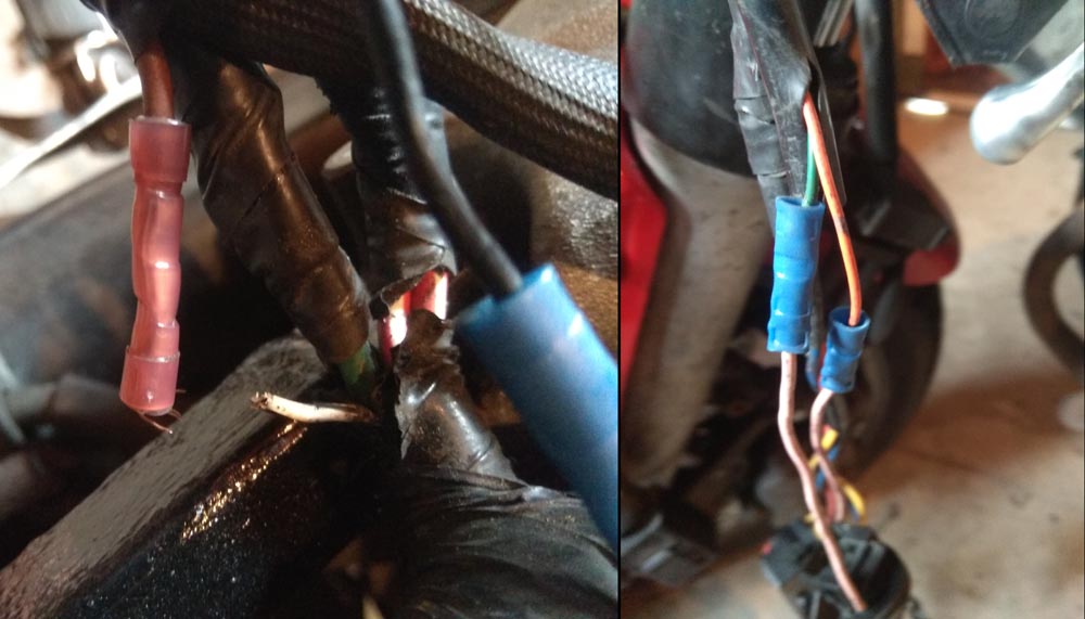
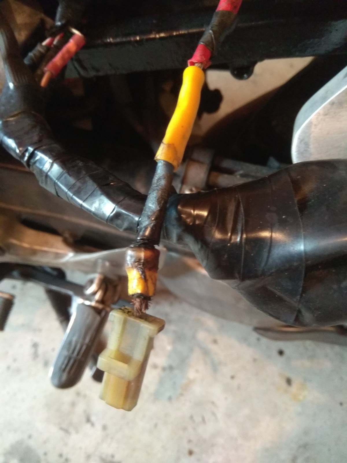
I need to change the very thin cable from my ACC socket to the quartet harness. does anyone have some suggestions for decent 2 wire connetors that will last maybe the type that have a rubber seal? The standard connectors are not great so i intend to remove the 9 pin plug and rubber boot and cut the cable out i will then add 3 new 2 wire connectors to replace the red white and black ones. Then i was thinking to wrap it all in self amalgamating tape. Should i add anything over the top as a extra layer of protection?
- Joined
- Oct 26, 2020
- Messages
- 1,779
- Location
- Makefield Highlands PA
- Bike
- 2016 ST1300P
- 2024 Miles
- 004382
Just a thought, if you don’t like the connectors, solder the wires together and heat shrink tube, you’ll never have another failure there. Otherwise, they are Hitachi connectors, available at many online retailers, don’t forget the crimper.I need to change the very thin cable from my ACC socket to the quartet harness. does anyone have some suggestions for decent 2 wire connetors that will last maybe the type that have a rubber seal? The standard connectors are not great so i intend to remove the 9 pin plug and rubber boot and cut the cable out i will then add 3 new 2 wire connectors to replace the red white and black ones. Then i was thinking to wrap it all in self amalgamating tape. Should i add anything over the top as a extra layer of protection?
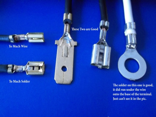
Also when crimping anything, don't use generic terminals and crimpers you find at auto-parts stores. They just crush terminal into crescent-shape, but don't squeeze OD inwards and increase contact surface area. End up with insufficient contact between wires and outside terminal. Resulting in higher resistance and heat. Gets worse over time with corrosion. You'll end up with burnt terminals, connectors and broken wires.
Best to use factory OEM connector & terminals. Most are Sumitomo with some Yazaki.
https://www.corsa-technic.com
https://www.bmotorsports.com/shop/index.php/cPath/109
https://www.easternbeaver.com
https://www.ksvlooms.com/collections/all-items
https://motorcycleconnectors.com
https://cycleterminal.com
https://www.automotiveconnectors.com/connectors-and-accessories.html
https://www.efihardware.com/products/c293/Connectors
http://www.vintageconnections.com/
https://kojaycat.co.uk/
https://www.3waycomponents.co.uk
Crimped terminals should look like this. Notice 2nd crimp over insulation for strain-relief. Get matching crimping-dies for particular terminals you're using. It will do both crimps at once to optimum pressure. I prefer TE/AMP Ergocrimp line of crimpers and dies.
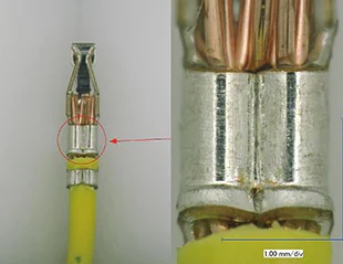
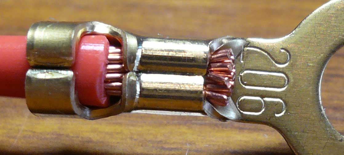
Then replace air between wire-strands at crimp with solder for much improved conductivity (lower heat) along with sealing wire-ends from moisture creeping down and causing green/black wire-disease.
credit: http://www.cycleterminal.com/crimp-tools.html
Best to use factory OEM connector & terminals. Most are Sumitomo with some Yazaki.
https://www.corsa-technic.com
https://www.bmotorsports.com/shop/index.php/cPath/109
https://www.easternbeaver.com
https://www.ksvlooms.com/collections/all-items
https://motorcycleconnectors.com
https://cycleterminal.com
https://www.automotiveconnectors.com/connectors-and-accessories.html
https://www.efihardware.com/products/c293/Connectors
http://www.vintageconnections.com/
https://kojaycat.co.uk/
https://www.3waycomponents.co.uk
Crimped terminals should look like this. Notice 2nd crimp over insulation for strain-relief. Get matching crimping-dies for particular terminals you're using. It will do both crimps at once to optimum pressure. I prefer TE/AMP Ergocrimp line of crimpers and dies.
Then replace air between wire-strands at crimp with solder for much improved conductivity (lower heat) along with sealing wire-ends from moisture creeping down and causing green/black wire-disease.
credit: http://www.cycleterminal.com/crimp-tools.html
Last edited:
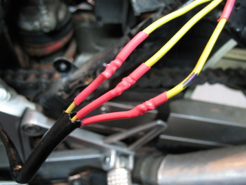
Yup, best to join wires with proper linesman/western-union knot with solder and adhesive heat-shrink tubing. Maintaining consistent diameter across joint is key to reducing stress-risers and fatigue damage over time. It's done this way in pro-motorsports (F1/MotoGP), military and aerospace applications for performance, reliability and durability. No need to pre-tin on larger stranded wires, makes it too difficult to tie knot.Just a thought, if you don’t like the connectors, solder the wires together and heat shrink tube, you’ll never have another failure there. Otherwise, they are Hitachi connectors, available at many online retailers, don’t forget the crimper.
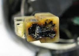
Here's ultimate solution to burnt connector between stator & RR on many VFRs and CBRs.
Last edited:
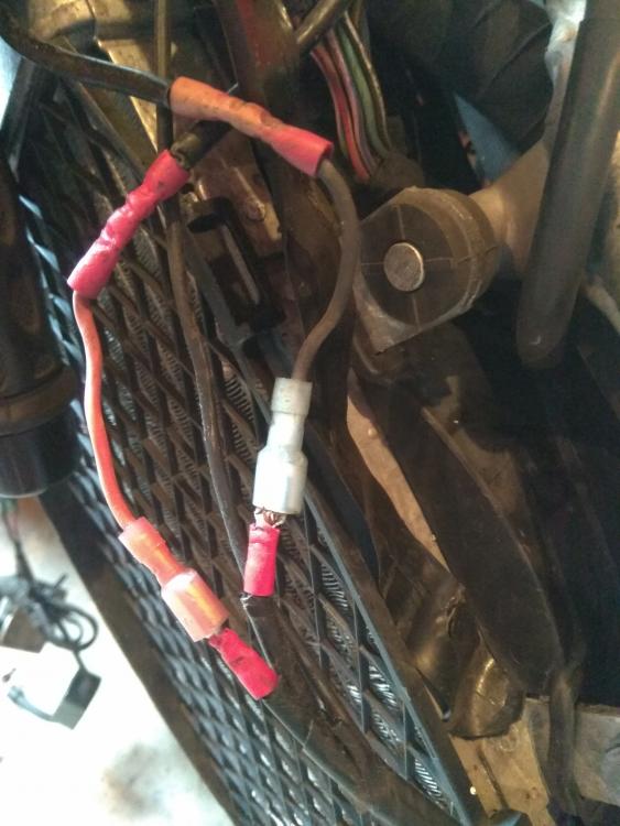
Thank you everyone. The normal connectors are bigger than they need to be and i dont need the 9 pin. I know by the quantity of cables coming out the bike certain cables are split and some are extra. so i dont need the turn signal wires or the constant 12v feed which is split to 2 so thats 4 cables to remove. I have a pin removal tool so will remove them from the 9 pin connecter plugged in at the loom and seal the holes. I was looking at something like these connectors in the picture. That said the idea of soldering the quartet direct to the items is appealing but makes changing or adding items harder in the future. It would depend on the size of the connectors shown if they are very bulky then solder direct maybe the way forward instead. I prefer decent soldering to crimping despite crimping being quicker. I could just go with 4x 2 pin plugs
Attachments

- Joined
- Oct 26, 2020
- Messages
- 1,779
- Location
- Makefield Highlands PA
- Bike
- 2016 ST1300P
- 2024 Miles
- 004382
Not positive these are the same as your picture, here is a two pin like your picture with the 9 pin and 2 pin. Shown with the international size gauge.Thank you everyone. The normal connectors are bigger than they need to be and i dont need the 9 pin. I know by the quantity of cables coming out the bike certain cables are split and some are extra. so i dont need the turn signal wires or the constant 12v feed which is split to 2 so thats 4 cables to remove. I have a pin removal tool so will remove them from the 9 pin connecter plugged in at the loom and seal the holes. I was looking at something like these connectors in the picture. That said the idea of soldering the quartet direct to the items is appealing but makes changing or adding items harder in the future. It would depend on the size of the connectors shown if they are very bulky then solder direct maybe the way forward instead. I prefer decent soldering to crimping despite crimping being quicker. I could just go with 4x 2 pin plugs

STRider
Site Supporter
Oh @Willsmotorcycle , we can never trust you again. You know the INTERNET standard is 'banana for scale' 


- Joined
- Nov 20, 2005
- Messages
- 9,514
- Location
- Cedar City, Utah
- Bike
- 12/04 ST 1300s
- 2024 Miles
- 000420
- STOC #
- 5901
Yup, best to join wires with proper linesman/western-union knot with solder and adhesive heat-shrink tubing. Maintaining consistent diameter across joint is key to reducing stress-risers and fatigue damage over time. It's done this way in pro-motorsports (F1/MotoGP), military and aerospace applications for performance, reliability and durability. No need to pre-tin on larger stranded wires, makes it too difficult to tie knot.
Link to NASA STD-8739.4a.pdf
Here's ultimate solution to burnt connector between stator & RR on many VFRs and CBRs.
Yeah, you had to make this repair on the V45 & V65 Sabres.
Oh @Willsmotorcycle , we can never trust you again. You know the INTERNET standard is 'banana for scale'
Are you sure about that?


Share: