
Hi folks!
In another thread by wjbertrand someone expressed an interest in some pictures of the Gold Valve install process. Since I was just starting this adventure I grabbed my camera and snapped pictures at key points in the process. The instruction sheets that come with the kit are, IMHO, not clear and complete. Hopefully these pictures, and my amateur explanations and those of Others who might want to chime in, will give you an idea of what is involved if you chose to install this kit.
I'll start at the point where the Damper Cartridge is sitting on the work bench. The process for getting to this point is described in excellent detail in the Honda Service Manual. If you don't have one yet, go get one!")
Just a few observations about the fork disassembly process:
1. If you have the Heli handlebar extenders on your bike you will have to remove both the handlebars and the Heli plates to get access to the 17mm Allen socket at the top of the fork cap.
2. That 17 mm fork cap is really tight! You will need a wrench (not a ball driver!) that fits real good and something to get some leverage. Sensitive ears should be vacated from the work area before attempting this!
3. The 6mm cap screw at the bottom of the shock is also on really tight. Don't try to use a ball driver like I did at first. I'm presently waiting for my replacement bolts to come in from HDL.: One thread on this forum suggests replacing both the seal and the bolt whenever you touch this. I think I will agree with that!
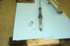
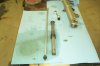
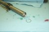
So. We Begin! Here's the Damper Cartridge.
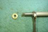
There is a compression valve that looks just like this new Gold Valve at the end of the tube. Push this in with your finger about an inch and you will see a groove with this cir clip hiding in it. You will need something sharp to get under this clip and work it out. Don't lose it!
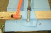
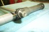
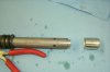
Now comes the chore of removing the shiny aluminum cap. Even though there is really nothing keeping this from sliding off, it most likely won't. First try threading the 6mm bolt into the compression valve and pull. If you don't end up with the cap, the valve, and a puddle of nasty oil in your hand, it's time to get a bit more insistant. Place the cartridge over a block and use a soft face hammer to tap on the top of the cap. If yours is stuck on like mine was, warming the cap with a heat gun and then tapping did the trick. Once I had it off once it would slip on an off easily. Go figure!
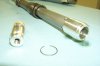
When you get the cap off you will get able to draw out the Honda compression valve.
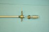
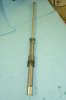
Push on the damper rod and the rebound valve and rod can be removed from the cartridge tube.
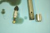
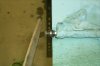
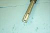
Looking at the end of the damper rod, the nut holding the rebound valve is held on by a heavy peening job on the end of the rod.
This is easily removed with a hand file. Keep going till you can remove the nut.
Sorry about the focus on the next two pictures. What you might have been able to see is that even though you got the nut off, the threads are actually bulged a bit by the peening process.
I used a file and a tap to straighten the threads enough that a thread re-conditioning die could be used to clean this mess up.
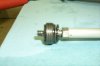
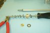
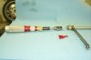
Time to get into the Race Tech Kit! I didn't get a picture of the kit before I played with all the pieces. Sorry! Below is a picture of how to arrange the parts for the rebound valve. I called Race Tech's support line and the tech I talked to confirmed that this is right. The pieces are packaged in plastic pouches. I found the check plate washer that is next to the spring in the same pouch as the R-19 shim pack, with an extra! So, you will have an extra check plate and a pretty brass nut extra for each damper assembly.
Nice! The forum troll ate my whole last post. Lets try this again
OK! Time to assemble the valve. This will challenge your manual dexterity a bit so no mid-job pictures!:
Assemble the top half of the valve. Make sure the cupped washer fits into the milled recess in the brass valve body and the check plate moves freely. Next install the R19 shim pack consisting of 11 thin spring steel plates. All the parts should be on the smooth portion of the rod bolt with just a little extra. Next install the base plate washer. While holding this together in one hand apply the Red gelled loctite provided in the kit to the Ny-lock nut and sparingly to the bolt threads. A word of caution, hold the rod/valve assembly either horizontal or a little downhill to prevent the loctite from flowing into the Gold Valve assembly. ( yes that happened to me!) While holding the valve assembly together get a wrench to hold the rod and tighten and torque the nut to 30 in-lbs. When tight the threads only partially engage the plastic locking ring on the nut.
Next, Race Tech wants you to polish the damper rod with some 600 grit sandpaper to reduce friction through the top cartridge bushing. it did seem a lot smoother when done. Clean everthing up, it's time to assemble this thing!
Oil the Cartridge tube and damper rod and assemble leaving the rebound valve exposed. Wrap the new packing strip around the valve and apply oil. Those little tabs on the packing are going to need help so put them on top and gently slide this into the tube pushing the ends down and it will go right in. You will also need to help them past the vent holes on the cartridge tube.
Next install the O-ring on the compression valve. This fits into the cartridge tube really tight. I used wheel bearing grease to lube the O-ring and the tube edge and cir-clip groove. Push in as gently as possible. I didn't see any chunks of O-ring sheared off so I think mine survived
Push the compression valve far enough in to install the cir-clip into the groove.
Almost done! Reach in with the allen bolt and pull the compression valve out to seat against the cir-clip. Install shiny aluminum cap, it should just slip on.
Your Done!
In another thread by wjbertrand someone expressed an interest in some pictures of the Gold Valve install process. Since I was just starting this adventure I grabbed my camera and snapped pictures at key points in the process. The instruction sheets that come with the kit are, IMHO, not clear and complete. Hopefully these pictures, and my amateur explanations and those of Others who might want to chime in, will give you an idea of what is involved if you chose to install this kit.
I'll start at the point where the Damper Cartridge is sitting on the work bench. The process for getting to this point is described in excellent detail in the Honda Service Manual. If you don't have one yet, go get one!
Just a few observations about the fork disassembly process:
1. If you have the Heli handlebar extenders on your bike you will have to remove both the handlebars and the Heli plates to get access to the 17mm Allen socket at the top of the fork cap.
2. That 17 mm fork cap is really tight! You will need a wrench (not a ball driver!) that fits real good and something to get some leverage. Sensitive ears should be vacated from the work area before attempting this!
3. The 6mm cap screw at the bottom of the shock is also on really tight. Don't try to use a ball driver like I did at first. I'm presently waiting for my replacement bolts to come in from HDL.
: One thread on this forum suggests replacing both the seal and the bolt whenever you touch this. I think I will agree with that!So. We Begin! Here's the Damper Cartridge.
There is a compression valve that looks just like this new Gold Valve at the end of the tube. Push this in with your finger about an inch and you will see a groove with this cir clip hiding in it. You will need something sharp to get under this clip and work it out. Don't lose it!
Now comes the chore of removing the shiny aluminum cap. Even though there is really nothing keeping this from sliding off, it most likely won't. First try threading the 6mm bolt into the compression valve and pull. If you don't end up with the cap, the valve, and a puddle of nasty oil in your hand, it's time to get a bit more insistant. Place the cartridge over a block and use a soft face hammer to tap on the top of the cap. If yours is stuck on like mine was, warming the cap with a heat gun and then tapping did the trick. Once I had it off once it would slip on an off easily. Go figure!
When you get the cap off you will get able to draw out the Honda compression valve.
Push on the damper rod and the rebound valve and rod can be removed from the cartridge tube.
Looking at the end of the damper rod, the nut holding the rebound valve is held on by a heavy peening job on the end of the rod.
This is easily removed with a hand file. Keep going till you can remove the nut.
Sorry about the focus on the next two pictures. What you might have been able to see is that even though you got the nut off, the threads are actually bulged a bit by the peening process.
I used a file and a tap to straighten the threads enough that a thread re-conditioning die could be used to clean this mess up.
Time to get into the Race Tech Kit! I didn't get a picture of the kit before I played with all the pieces. Sorry!
Below is a picture of how to arrange the parts for the rebound valve. I called Race Tech's support line and the tech I talked to confirmed that this is right. The pieces are packaged in plastic pouches. I found the check plate washer that is next to the spring in the same pouch as the R-19 shim pack, with an extra! So, you will have an extra check plate and a pretty brass nut extra for each damper assembly.Nice! The forum troll ate my whole last post.
Lets try this againOK! Time to assemble the valve. This will challenge your manual dexterity a bit so no mid-job pictures!
:Assemble the top half of the valve. Make sure the cupped washer fits into the milled recess in the brass valve body and the check plate moves freely. Next install the R19 shim pack consisting of 11 thin spring steel plates. All the parts should be on the smooth portion of the rod bolt with just a little extra. Next install the base plate washer. While holding this together in one hand apply the Red gelled loctite provided in the kit to the Ny-lock nut and sparingly to the bolt threads. A word of caution, hold the rod/valve assembly either horizontal or a little downhill to prevent the loctite from flowing into the Gold Valve assembly. ( yes that happened to me!) While holding the valve assembly together get a wrench to hold the rod and tighten and torque the nut to 30 in-lbs. When tight the threads only partially engage the plastic locking ring on the nut.
Next, Race Tech wants you to polish the damper rod with some 600 grit sandpaper to reduce friction through the top cartridge bushing. it did seem a lot smoother when done. Clean everthing up, it's time to assemble this thing!
Oil the Cartridge tube and damper rod and assemble leaving the rebound valve exposed. Wrap the new packing strip around the valve and apply oil. Those little tabs on the packing are going to need help so put them on top and gently slide this into the tube pushing the ends down and it will go right in. You will also need to help them past the vent holes on the cartridge tube.
Next install the O-ring on the compression valve. This fits into the cartridge tube really tight. I used wheel bearing grease to lube the O-ring and the tube edge and cir-clip groove. Push in as gently as possible. I didn't see any chunks of O-ring sheared off so I think mine survived
Push the compression valve far enough in to install the cir-clip into the groove.
Almost done! Reach in with the allen bolt and pull the compression valve out to seat against the cir-clip. Install shiny aluminum cap, it should just slip on.
Your Done!
Attachments
-
 P0002554.jpg218.8 KB · Views: 345
 -
 P0002556.jpg233.8 KB · Views: 259
 -
 P0002580.jpg235.6 KB · Views: 248
 -
 P0002557.jpg331.1 KB · Views: 261
 -
 P0002560.jpg234.6 KB · Views: 230
 -
 P0002561.jpg252.4 KB · Views: 238
 -
 P0002562.jpg314.2 KB · Views: 220
 -
 P0002563.jpg166.2 KB · Views: 203
 -
 P0002564.jpg225.6 KB · Views: 190
 -
 P0002572.jpg261.5 KB · Views: 267
 -
 P0002574.jpg251 KB · Views: 242
 -
 P0002575.jpg286.3 KB · Views: 233
 -
 P0002576.jpg292.8 KB · Views: 180
 -
 P0002577.jpg278.8 KB · Views: 176
 -
 P0002579.jpg281.9 KB · Views: 139
 -
 P0002578.jpg200.8 KB · Views: 198
Last edited by a moderator: