
STRider
Site Supporter
Greetings fellow road grimed astronauts.
I got the itch to upgrade my 2012 ST1300 with self-cancelling turn signals. I won't debate the merits of this choice here, but I will endeavor to cut through the volumes of posts related to how to install it that preceded this one to hopefully provide the definitive guide and a new basis for discussion (more like fear)") .
.
First, the "ST2 Turn System, Self-Cancelling Turn Signal Module" as it's properly known can be had from a number of sources. However as many of you know if you visit their website, click on the compatibility check button, select your model from the drop-down lists and submit your request using your email, you will be greeted with a persistent, but polite, stream of emails first confirming that yes, the ST1300 is compatible with the ST2 Turn System (hereafter ST2-TS) along with some steep discounts for the ST2-TS along with their Smart Brake Module. I was able to buy mine with a 40% discount. It started out at 30% and after playing coy for a few messages the discount increased to 40%. Just before Christmas they ran a 50% off promotion where "the ENTIRE purchase amount will be donated to "The Bike Experience" – a charity that teaches disabled motorbike riders how to ride again following an accident or disability."
The lesson? Don't buy at list price.
Ordering from ST2 directly means doing business with the company in Romania from which your unit will be shipped. My ST2-TS was ordered on Nov 24th, arrived at customs in Chicago on the 28th where it sat for 14 days before being released into the USPS and delivered on Dec 15th; 22 days later. Apart from the delay through customs the experience was very smooth.
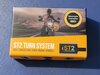
So here's what you get:
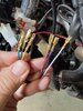
The first thing I did was dispense with the bullet and blade connectors on the unit's wires.
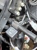
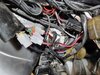
After removing the left middle cowl I traced the bundle of wires from the left switchpod to a cluster of connectors tucked below the frame forward of the left valve cover. Pull that out and you'll find a red and black 9-pin Hitachi connector ad the end of those wires. The red connector is the one which passes the turn signal and 4-way flasher circuit through the switchpod.
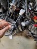
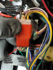
The switchpod end is the male connector, and the wiring harness side is female. I crimped the appropriate terminals onto each stripped wire.
All 9 positions are occupied in that connector and since the ST2-TS only taps into three of those wires - left/right/common - six lengths of suitable wire must be sourced to serve as pass throughs for the other six wires; preferably wires of different colors, ideally colors that match those other six. I could only manage to satisfy the preferably criteria.
The wire length should be twice the length of the free wire extending from the the bundle coming out of the module. If I were to do this again I would strip back an additional 1 to 2" of the outer sheath to give me greater freedom in positioning the two signal connectors and the power wires.
For power I used the last unused connector remaining on my Quartet Harness (henceforth QH). This was the 9-pin connector, of which I needed only two terminals - switched 12VDC power and ground. If you haven't already installed the QH and the 9-pin connector it plugs into is free, you can similarly use it to power the ST2-TS. Other wise use any available switched connector on the QH. If you're with me this far and are similarly committed to not cutting or tapping into wires, then you'll find a source. Otherwise, use those wire taps!
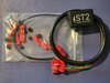
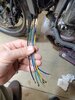
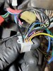
Here's my ST2-TS in the initial test configuration. Only the turn signal wires and power have been connected. This confirmed that I had it wired correctly.
Next I prepared and added the passthru wires for the remaining 6 terminals in each connector.
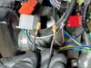
Here's completed harness Ver 1.
I removed the windshield and upper cowl so I could access the upper cowl stay. It was on the short horizontal tube which backs the left mirror bracket where I mounted it using a single long zip tie and used some foam gasket tape to cushion it and discourage rotation around the smooth tube. I later saw that others had posted using that same location with varying numbers of zip ties.
I wrapped the loose wires in electrical tape, reconnected and tucked everything away like before. It was at this point I concluded that a little extra length between those two new connectors, as well as on the power wire would make tucking away all of the wiring a little easier and neater. Had I stripped back more of the sheath on the ST2-TS wire bundle I likely would've made those passthrough wires longer too. However as I think about it, just making the free length of the power wires longer would've done the job. As is now it pulls the whole QH harness bundle of connectors to the rear making it rather cramped in the vicinity of the left faring pocket and the parts inside the middle cowl. Longer power wires would allow that QH bundle to be farther forward in the vicinity of the ST2-TS unit itself behind the middle cowl. C'est la vie. It works.
Before I move to the switchpod modification, I discovered that the 4-way flashers didn't work. I failed to research this thoroughly enough on this site prior to starting the install. I didn't know this was an issue until I went looking for the solution, which is simple if you know about it before making your passthru wires and crimping the terminals.
Long story short, the ground wires for the turn signals and the 4-way flashers pass through the OEM connector independently, while the left & right signal wires from the turn switch and 4-way flasher switch do not. Those signal wires join together on the switchpod side of the connector. The ST2-TS is designed with a signal passthrough function for this purpose, but to do so the 4-way flasher's ground must be tied to that of the turn signals. Easy peasy if you know this ahead of time. I didn't and had to strip the left side of the bike a second time in three days to make this modification once I learned about it.
I had used black wire for the 4-way flasher's ground wire passthrough. I pulled it from the opposite connector and looped it back into the connector where the tan wire input to the ST2-TS. I reconnected and confirmed that the 4-way flashers now worked! Yea ha!
I clipped the terminals from the male end of the black wire (the 4-way's ground) and the female from the tan wire going into the ST2-TS and them doubled them up on the same female terminal and reinserted them into the connector. Which position they occupy in the connector is irrelevant as those wires are now electrically connected (I said that because I think they're reversed from where they started).
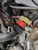
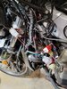
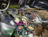
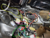
Here's the whole mess under my left middle cowl before I retaped the wires and tucked everything away.
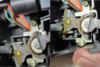
Onto the switchpod. First remove the two external screws which hold the pod together and on the handlebar. Separate the top from the bar revealing the bottom which remains attached to the bar. I made the mistake of removing the the larger screw which retains the curved piece of metal clamping the larger plate to the bar. Once I removed the larger screw and the lower part of the pod I could not get it back into place for the life of me. There's a screw in the underside of that plate which acts as a locating pin for the lower pod. Perhaps my grip prevented it from seating as it should but I found if I released the lower half of the pod by removing the small screw, leaving those plates attached to the bar, everything came apart and went together much easier. YMMV
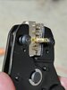
With that plate out of the way, you can see where the foam discs must be placed to prevent latching.
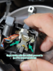
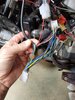
Here is the switch with the lever removed. The white block is moved side-to-side to switch on either signal. You can see the colors of the wires that must be located at the connector - blue/right, orange/left and grey/common.
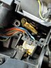
The ST2-TS uses small foam discs to prevent the switch from latching in the on position. Here are the 0.10" versions in place.
Assembly is the reverse of disassembly.
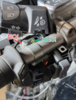
This is what the final project looks like. Yes I tucked the QH connectors into their cover, and copious amounts of dielectric grease live inside the connectors.
Now everything I did can be done with the connectors provided in the kit. The key difference from their supplied directions is that, in addition to cutting the gray common wire for the turn signals, you must also cut the pink wire and double it up with the gray wire in the bullet connector. You'll then want to tape off the loose end of the pink wire or remove it from the red connector all together as it's no longer needed...
Now if you haven't figured it out yet, I am aggressively biased toward using the proper connectors and crimpers to do this type of modification. I'd love to spend your money for you, but your wife, husband, significant other, heirs, the IRS... might object. But hear me out. The vast majority of the headaches I've experienced in my car and motorcycle career has been with shade tree mechanic electrical modifications... Like unsealed bullet connectors, and wire taps. The connectors in this very affordable kit from Amazon (I know!) and either of these crimpers will make not just this but dozens of projects cleaner, more professional and most important reliable. And if you follow the approach I've preached over and over, no OEM wire will be harmed in this project!!
Many thanks to @Catmandu2 , @barrysegal , @MaxPete , @RaYzerman , @Portpandon , @Dr who , @Al-Hala, @DavidR8 (where are they now?) and numerous others through which your discussions made my flasher solution obvious.
I'll stick around for questions...
Terminal kit
Simple slightly less expensive crimper
Interchangeable anvil cripers plus wire strippers
I got the itch to upgrade my 2012 ST1300 with self-cancelling turn signals. I won't debate the merits of this choice here, but I will endeavor to cut through the volumes of posts related to how to install it that preceded this one to hopefully provide the definitive guide and a new basis for discussion (more like fear)
.First, the "ST2 Turn System, Self-Cancelling Turn Signal Module" as it's properly known can be had from a number of sources. However as many of you know if you visit their website, click on the compatibility check button, select your model from the drop-down lists and submit your request using your email, you will be greeted with a persistent, but polite, stream of emails first confirming that yes, the ST1300 is compatible with the ST2 Turn System (hereafter ST2-TS) along with some steep discounts for the ST2-TS along with their Smart Brake Module. I was able to buy mine with a 40% discount. It started out at 30% and after playing coy for a few messages the discount increased to 40%. Just before Christmas they ran a 50% off promotion where "the ENTIRE purchase amount will be donated to "The Bike Experience" – a charity that teaches disabled motorbike riders how to ride again following an accident or disability."
The lesson? Don't buy at list price.
Ordering from ST2 directly means doing business with the company in Romania from which your unit will be shipped. My ST2-TS was ordered on Nov 24th, arrived at customs in Chicago on the 28th where it sat for 14 days before being released into the USPS and delivered on Dec 15th; 22 days later. Apart from the delay through customs the experience was very smooth.
So here's what you get:
- The unit with bullet and blade connectors already in place.
- Mating bullet connectors to attach to the bike's wiring - 3 each male and female
- 2 blade style wire taps to use for power
- Several pill size foam discs - 0.10 and 0.20" thick (I got six - 0.10" discs and seven - 0.20" discs). These are used to convert the turn signal switch from latching to momentary.
The first thing I did was dispense with the bullet and blade connectors on the unit's wires.
After removing the left middle cowl I traced the bundle of wires from the left switchpod to a cluster of connectors tucked below the frame forward of the left valve cover. Pull that out and you'll find a red and black 9-pin Hitachi connector ad the end of those wires. The red connector is the one which passes the turn signal and 4-way flasher circuit through the switchpod.
The switchpod end is the male connector, and the wiring harness side is female. I crimped the appropriate terminals onto each stripped wire.
All 9 positions are occupied in that connector and since the ST2-TS only taps into three of those wires - left/right/common - six lengths of suitable wire must be sourced to serve as pass throughs for the other six wires; preferably wires of different colors, ideally colors that match those other six. I could only manage to satisfy the preferably criteria.
The wire length should be twice the length of the free wire extending from the the bundle coming out of the module. If I were to do this again I would strip back an additional 1 to 2" of the outer sheath to give me greater freedom in positioning the two signal connectors and the power wires.
For power I used the last unused connector remaining on my Quartet Harness (henceforth QH). This was the 9-pin connector, of which I needed only two terminals - switched 12VDC power and ground. If you haven't already installed the QH and the 9-pin connector it plugs into is free, you can similarly use it to power the ST2-TS. Other wise use any available switched connector on the QH. If you're with me this far and are similarly committed to not cutting or tapping into wires, then you'll find a source. Otherwise, use those wire taps!
Here's my ST2-TS in the initial test configuration. Only the turn signal wires and power have been connected. This confirmed that I had it wired correctly.
Next I prepared and added the passthru wires for the remaining 6 terminals in each connector.
Here's completed harness Ver 1.
I removed the windshield and upper cowl so I could access the upper cowl stay. It was on the short horizontal tube which backs the left mirror bracket where I mounted it using a single long zip tie and used some foam gasket tape to cushion it and discourage rotation around the smooth tube. I later saw that others had posted using that same location with varying numbers of zip ties.
I wrapped the loose wires in electrical tape, reconnected and tucked everything away like before. It was at this point I concluded that a little extra length between those two new connectors, as well as on the power wire would make tucking away all of the wiring a little easier and neater. Had I stripped back more of the sheath on the ST2-TS wire bundle I likely would've made those passthrough wires longer too. However as I think about it, just making the free length of the power wires longer would've done the job. As is now it pulls the whole QH harness bundle of connectors to the rear making it rather cramped in the vicinity of the left faring pocket and the parts inside the middle cowl. Longer power wires would allow that QH bundle to be farther forward in the vicinity of the ST2-TS unit itself behind the middle cowl. C'est la vie. It works.
Before I move to the switchpod modification, I discovered that the 4-way flashers didn't work. I failed to research this thoroughly enough on this site prior to starting the install. I didn't know this was an issue until I went looking for the solution, which is simple if you know about it before making your passthru wires and crimping the terminals.
Long story short, the ground wires for the turn signals and the 4-way flashers pass through the OEM connector independently, while the left & right signal wires from the turn switch and 4-way flasher switch do not. Those signal wires join together on the switchpod side of the connector. The ST2-TS is designed with a signal passthrough function for this purpose, but to do so the 4-way flasher's ground must be tied to that of the turn signals. Easy peasy if you know this ahead of time. I didn't and had to strip the left side of the bike a second time in three days to make this modification once I learned about it.
I had used black wire for the 4-way flasher's ground wire passthrough. I pulled it from the opposite connector and looped it back into the connector where the tan wire input to the ST2-TS. I reconnected and confirmed that the 4-way flashers now worked! Yea ha!
I clipped the terminals from the male end of the black wire (the 4-way's ground) and the female from the tan wire going into the ST2-TS and them doubled them up on the same female terminal and reinserted them into the connector. Which position they occupy in the connector is irrelevant as those wires are now electrically connected (I said that because I think they're reversed from where they started).
Here's the whole mess under my left middle cowl before I retaped the wires and tucked everything away.
Onto the switchpod. First remove the two external screws which hold the pod together and on the handlebar. Separate the top from the bar revealing the bottom which remains attached to the bar. I made the mistake of removing the the larger screw which retains the curved piece of metal clamping the larger plate to the bar. Once I removed the larger screw and the lower part of the pod I could not get it back into place for the life of me. There's a screw in the underside of that plate which acts as a locating pin for the lower pod. Perhaps my grip prevented it from seating as it should but I found if I released the lower half of the pod by removing the small screw, leaving those plates attached to the bar, everything came apart and went together much easier. YMMV
With that plate out of the way, you can see where the foam discs must be placed to prevent latching.
Here is the switch with the lever removed. The white block is moved side-to-side to switch on either signal. You can see the colors of the wires that must be located at the connector - blue/right, orange/left and grey/common.
The ST2-TS uses small foam discs to prevent the switch from latching in the on position. Here are the 0.10" versions in place.
Assembly is the reverse of disassembly.
This is what the final project looks like. Yes I tucked the QH connectors into their cover, and copious amounts of dielectric grease live inside the connectors.
Now everything I did can be done with the connectors provided in the kit. The key difference from their supplied directions is that, in addition to cutting the gray common wire for the turn signals, you must also cut the pink wire and double it up with the gray wire in the bullet connector. You'll then want to tape off the loose end of the pink wire or remove it from the red connector all together as it's no longer needed...
Now if you haven't figured it out yet, I am aggressively biased toward using the proper connectors and crimpers to do this type of modification. I'd love to spend your money for you, but your wife, husband, significant other, heirs, the IRS... might object. But hear me out. The vast majority of the headaches I've experienced in my car and motorcycle career has been with shade tree mechanic electrical modifications... Like unsealed bullet connectors, and wire taps. The connectors in this very affordable kit from Amazon (I know!) and either of these crimpers will make not just this but dozens of projects cleaner, more professional and most important reliable. And if you follow the approach I've preached over and over, no OEM wire will be harmed in this project!!
Many thanks to @Catmandu2 , @barrysegal , @MaxPete , @RaYzerman , @Portpandon , @Dr who , @Al-Hala, @DavidR8 (where are they now?) and numerous others through which your discussions made my flasher solution obvious.
I'll stick around for questions...
Terminal kit
Simple slightly less expensive crimper
Interchangeable anvil cripers plus wire strippers
Attachments
-
 1.2 MB Views: 18
Last edited:


