Article [13] ST1300 - Rostra Cruise Control Installation

I've started gathering parts to do the cruise control upgrade and thanks to this thread hopefully I'll be able to manage it. I have a couple of questions before I start that I'm hoping someone can answer.
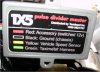
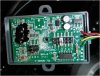
2) I receive my pulse divider and they have now gone to what I am guessing is more of printed circuit type with the C8 cannot be cut off. Am planning on leaving it alone.
3) And yes it is cheaper on the Centrodyne site but shipping is more than the unit so taxicable is still cheaper.

Thanks for any inputs

I'm still working on the settings for my pulse divider. Still waiting for a response from Centrodyne.

Not sure what shipping you picked but it was $11 UPS ground for me direct from Centrodyne.
 
Here's some of my tips.

On my GW switch I ran a third Hitachi plug with the wires that were left over in the bundle. All the Hitachi plugs were from Eastern Beaver. I ended up wiring the RVS switch for the lights I'll be putting on the mirror mounts.
Also with the GW switch now the throttle tube is too long. My Kaoko throttle lock would no longer work so I went back to the OEM bar end. I did make a spacer from a dirt bike aluminum bar I had cut down. I did have to drill the I.D. and turn the O.D. down on my lathe. IIRC it was about .475" long.

Another tip for you is to drill the Futoba arm out small and file 2 flats on the side like the stud on the FI rail stud. There were barely enough threads and with the flats there aren't many threads grabbing to begin with. I ended up grinding the arm thinner and grinding a flat on the side where the pully wheel is. This flares out and doesn't let the Futoba sit flat against the wheel.

I also mounted my cable connection low and farther back. I had issues with the cable getting jammed under the airbox.

I also didn't pin the GW switch to the bar, all I did was grind the tab off the switch. If you don't have risers the bottom of the switch will contact the tank. There is an small angular plastic piece I'm going to either file or cut off.

When I mounted the CC control box didn't use any bracket. I just used one of the mounting holes and bolted it right to the frame.

On the CC wiring I cut the bulkhead connectors off and shortened the wires because they so long.

BTW- I have a LIN3 strobe and have no issues. You will have a problem if you have LED tail/brake bulbs.
 
I tried the second setting up from lowest and the lowest, which seemed worse. I was out riding it and when I went to change it I grabbed the jumper with needlenose pliers and it was so cold the plastic on the jumper broke so I couldn't change it again. I have another jumper so I should be able to test it a bit later today.
 
Okay. I set the gain at max setting and it works much better now. At 50mph set it was pretty jerky before on throttle input. Now it's pretty smooth. Over 60 it's perfectly smooth, which I would only use it over 65 anyway most likely.

I tried the divide by 4 setting and it was really smooth at any speed but had issues holding the speed, which is why it was probably so smooth.
 
I have a PDF document Centrodyne sent me of the Z063 with all the specs. If anyone wants a copy PM me with their e-mail.
 
Help!!!
Started installing my cruise control with the backlit GW switch this week and don't seem to have the wiring right. Part of my problem is I'm slightly color blind and have a very hard time distinguishing shades of colors so the instructions are hard to follow. I know I missed one step that snowmoer called out, but I'm not sure what wire to connect. Calls out to hook up 12V power to black/yellow. On my harness i think that is the brake line. I think I have the 9 pin connector correct, I can start the bike and all the lights work. Attached is my wire diagram, I used pin locations instead of color. Any help would be greatly appreciated.
Thanks,
Don
removed the diagram as it was wrong and didn't want anyone to use by mistake
 
Help!!!
Started installing my cruise control with the backlit GW switch this week and don't seem to have the wiring right. Part of my problem is I'm slightly color blind and have a very hard time distinguishing shades of colors so the instructions are hard to follow. I know I missed one step that snowmoer called out, but I'm not sure what wire to connect. Calls out to hook up 12V power to black/yellow. On my harness i think that is the brake line. I think I have the 9 pin connector correct, I can start the bike and all the lights work. Attached is my wire diagram, I used pin locations instead of color. Any help would be greatly appreciated.
Thanks,
Don

I went by snowmoer color codes so I can't help you out. Can you have someone come over and tell you the colors?
 
I have my son coming over tomorrow, maybe he'll see something i don't. I think I am using the same color codes as snowmoer.
 
Make sure you hook up the extra power wire to the RVS switch while you're in there in case you want to use that switch to turn something on. I wired mine to turn on my LED lights.
 
Found part of the problem, me, failure to follow directions. Had one of the brake lights hooked to to Black/yellow wire. Fixed that and added power to the black/yellow and it almost checks out. The brake, accel, and decel all check out but the VSS doesn't pass the checkout. Recheck the connection and the switch position and both seem correct. I put the bike up on its stand and spun the tire, still no checkout. Any ideas.
 
I think so. I tapped into the pink with green stripe. If I tapped into the right one, there were actually two of them side by side going into the same terminal location. Connected that to the yellow pulse divider wire, connected the green pulse divider wire to the rostra gray wire. I have power on the red wire of the pulse divider and the brown wire of the rostra
 
I was sent a different pulse divider than any pictured. Think it's an updated version. Did a divide by 2 and set the other pin on position B. It works great!!!! See pics of new divider. Getting errors on uploading will try later
 

Attachments

  • TX5.jpg
    TX5.jpg
    52.3 KB · Views: 98
  • TX5 inside.jpg
    TX5 inside.jpg
    35.6 KB · Views: 105
Last edited:
post note: rostra now has a pulse divider for sale cheaper than the one mentioned above . no capacitors to clip or pins to move. They have pulse dividers that divide by 2 or 4 i purchased the divide by 4 set my rostra at 24000 pules per mile. this is now my fourth cruise install on motorcycle and so far still loving the rostra electronic servo unit . I first installed cruise on my 96 pc800, then on my2001 concourse 1000 then my 05 st 1300(gone but not forgotten) and now on my new 07 st1300 this was the first using the gold wing switch and thanks for all of the advice on the gold wing switch wire colors
 
I installed mine lower than in this article and with the cable pointed horizontally, but I don?t know if Honda speakers will fit.
 

Attachments

  • P01.JPG
    P01.JPG
    401.7 KB · Views: 144
ImageUploadedByTapatalk1334522509.898679.jpgPicture.
Here is a picture of the inside of the Z063 signal divider.
Note no blue capacitor, #8 is the same color as the rest.
 
Back
Top Bottom