How do you like the cruise control? I am looking for one for my STTo view this article, click on the link to the attached PDF file.
Rostra cruise control installation by altexst1300.

Article [13] ST1300 - Rostra Cruise Control Installation
- Thread starter altexst1300
- Start date
-
- Tags
- 1300 cruise control
I wouldn't want a bike without it! I had the vacuum version on my 2000 ST1100. The Rostra electronic kit works fine if you can install it. Takes a lot of patience and time, some creativity and ingenuity. Also takes a bit of adjustment to get it working smoothly. I would do it again.
Works great, i paired it with a police switch so I have all the functions in a stock control.How do you like the cruise control? I am looking for one for my ST
Shawn K
Professional Cat Confuser
I'm on my second bike with a Rostra cruise. I won't ride a bike without electronic cruise now.
Looking forward to riding more. I am in the Bangor Maine area...not many ST riders.Welcome to the ST-Owners forum Tony.
That’s the nice thing about the ST, friends are just a few enjoyable hours away.Looking forward to riding more. I am in the Bangor Maine area...not many ST riders.
I ordered the cruise control...with control pad. Was it difficult to install? Or should I leave it to my Honda dealership?
Tony
Tony
If you can do basic mechanical work and competent wiring, you can do it with our help.I ordered the cruise control...with control pad. Was it difficult to install? Or should I leave it to my Honda dealership?
I would expect a dealer to decline for liability reasons, but I'd rather do it myself anyway.
Thanks for the info...I am good at stuff like that and will look at vids online first and go slow. I am doing the USA 4 corners ride next year so I want to be ready.
I'm in VA if you happen to pass this way.Thanks for the info...I am good at stuff like that and will look at vids online first and go slow. I am doing the USA 4 corners ride next year so I want to be ready.
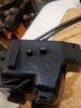
The main installation steps are finding a good place to mount the servo, connecting the throttle cable to the throttle, and connecting the wiring. The last part is my specialty. I've been installing car stereo and CC since the days of 8-tracks.
I have bought, but haven't yet installed the Rostra on my 1100, but I did put one on my Nighthawk 750.
Thanks Larry...I will keep you posted when I do my 4 corners ride...I will be coming right through Richmond.I'm in VA if you happen to pass this way.
The main installation steps are finding a good place to mount the servo, connecting the throttle cable to the throttle, and connecting the wiring. The last part is my specialty. I've been installing car stereo and CC since the days of 8-tracks.
I have bought, but haven't yet installed the Rostra on my 1100, but I did put one on my Nighthawk 750.
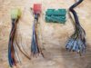
I got cruise in...man there are a ton of wires...I am going to read up on it then determine if I can handle this...Thanks Larry...I will keep you posted when I do my 4 corners ride...I will be coming right through Richmond.
Larry can you call me sometime so I can talk to you about wiring...207-852-8509 Tony
Shawn, did you install cruise yourself?I'm on my second bike with a Rostra cruise. I won't ride a bike without electronic cruise now.
Shawn K
Professional Cat Confuser
Yes, both times.Shawn, did you install cruise yourself?
can you call me when you get a min...I have some questions about the wires...207-852-8509Yes, both times.
Tony
Tony, I'm the wire guy, but Shawn can tell you specifics about the ST1300 installation.can you call me when you get a min...I have some questions about the wires...207-852-8509
Tony
Hi everyone, I have been planning this project for a while now. Unfortunately, the switch i was able to source has a green connection not blue and the housing dosen't have anything printed on it. Does anyone have wiring explanation like 4jranch did for this type of switch, some of the wires do not seem to correspond correctly?I am writing this for others that may look at this and be intimidated by the wiring instructions. I really appreciate all that have contributed to this thread as each post has helped me get to the point where I finally bit the bullet and did the deed. I will add some of my insights and pictures that may help others.
I had previously installed the vacuum type of cruise control so I was not worried about the mechanical aspect. The wiring was my worry.
First there are wires on both the cruise control unit (CC) and the Goldwing switch (GWS) that are not used. These I wrapped carefully with electrical tape, some I cut shorter for convenience. The Centrodyne divider had all wires connected. In the next few paragraphs I will try to list each wire from each unit and where it attaches.
I will use the following abbreviations for colors.
Black- Bl
Blue- Bu
Brown- Br
White- W
Red- R
Yellow- Y
Gray- Gy
Green- G
Violet- V
Sky Blue- SBu
Light Green- LtG
Orange- O
Light Blue- LtBu
Pink- P
CC (cruise control unit)
Gy- to W on Centrodyne divider
Bu- to Bu on the left coil or Bu/Y on the right coil
Br- to a 12v switched + from the Quartet harness (Q) or other (+) source
Bl- to ground in Q harness or other (-) source
V- to brake switch cold, G/Y from 9 pin connector from right handlebar switch
R/Br- to Bl/G from GW switch
G- to W/Y from GW switch
Y- to W/Bu from GW switch
O- not used
LtG- not used
J Auxiliary speed connector- not used
K 4 pin switch cut off and not used with GW switch
L 2 pin connector- not used
GW switch ( Goldwing switch- #35130-MCA-A21 with back light)
W- to Y/Bl in 9 pin connector
Bl/W- to Bl in 9 pin connector
G/Y- to G/Y in 9 pin connector, this is the brake cold wire
W/G- to Y/G in 9 pin
Br/R- to Bl/R in 9 pin
Y/R- to Y/R in 9 pin
Bu/W- to Bu/W in 9 pin
Bl/G- to CC- R/Br
W/Y to CC- G
W/Bu- CC- Y
Bl/Y- to (+) from Q (switched)
LtBu/Bl- to (+) from Q (switched)
G-to gound (-) from Q
Y/W- not used, available for another circuit on the reverse on/off switch
Bl/R- not used, available for another circuit on the reverse on/off switch
Br- not used, available for another circuit on the reverse on/off switch
Bl/Br- not used, available for another circuit on the reverse on/off switch
G/W – not used
Other end near GW switch
W/G- attached to brake switch
G/Y- attached to brake switch
Bl/Y- not used, capped off
G/W- not used, capped off
Centrodyne Unit
W- to Gy from CC
G- to P/G found at the 27 pin connector on left of bike under gas tank area
R- to (+) in Q harness
Bl- to (-) in Q harness
I will attach a copy of my wiring diagram.
All (+) sources should be switched, in other words no on when the key is off and each should have an in line fuse. I used the Quartet harness for most of mine.
My Centrodyne divider is set at divide by 2 and high gain and I did not clip off the #8 capacitor, the newer units may not need these settings.
My throttle grip needed to be cut off by about ? inch as the GW switch is wider.
I'm trying to get some of the prep work done for my Rostra installation this winter and need some advice. The GW switch I've got is the 35130-MCA-A21 and I've deconstructed the blue connector. I'm ready to cut off the old connectors and crimp on the new ones and was wondering if anyone, having done the install, has shortened up the rather long cable that comes with the GW switch, and if so, how much did you cut off?
Sadlsor
Site Supporter
- Joined
- Jan 15, 2020
- Messages
- 4,284
- Age
- 66
- Location
- Birmingham, Alabama
- Bike
- 2008 ST1300A
- STOC #
- 9065
That's on my list, complete with the requisite GoldWing pod.
Meaning, I have not done this yet.
However, it would seem that you want enough cable to allow lock-to-lock handlebar movement, but not much more than that.
I've read this entire thread shortly after joining, so I will have much to revisit.
Which specific cable are you referring to in the GW switch?
I foresee following the path of the existing cables coming from the right grip, just bundling them together as best you can.