Hi to all can anyone shed light on the handle bar buttons, i am having difficulty to find out what is suppose to do what, bought a ex cop st1100 and handle bar buttons seem not to work, like no mirror functions and some buttons on right hand bar seem to do nothing at all.

2003 ST 1100 PAN EURO
- Thread starter theo
- Start date
Theo, The right hand police spec switch would have carried out the normal functions plus emergency lighting and noise. From memory the police functions should be numbered, I think 1 to 5. But that is again from memory.
Sorry but I don't understand the mirror bit.
Welcome from Northumberland, England.
Upt.
Sorry but I don't understand the mirror bit.
Welcome from Northumberland, England.
Upt.
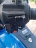
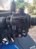
R/hand bar, I've got no idea what these buttons do or suppose to do
Attachments
-
 71.6 KB Views: 32
 -
 74.3 KB Views: 30
Uncle Phil
Site Supporter
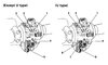
Police switch wiring -
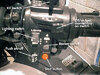
As far as I'm aware Honda Supplied the switch but it was down to individual specs as to what switch did what. I think I see they're numbered up to 7, what happened to my memory....oh yes....Scotch.
You can basically do what you want with them, originally they would operate headlight modulators, blue and red lights front, side and rear. Rear mast lights, wailers etc.
I think the top switch was spring loaded so it wouldn't stay in 3? But can't be sure. Damn Scotch.
In most of the UK Sonic Communications fitted out the police spec Hondas.
Upt.
Hound
Cave Canem
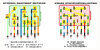
On UK bikes, switch o-1-2-3 controlled strobes and siren. o was off, 1 was front blues, 2 added siren, 3 was a non-locking (momentary) position for "yelp". 4 and 5 were rear blues pole and rear reds. They varied slightly as forces rearranged the occasional function to their preference.
There were two types; one had controls for the sidelights and headlights as Uncle Phil illustrates, and one used that switch for alternative functions (the lighting being assigned to the ignition wiring).
If your switch marked o-6-7 has no effect on your lights, you have an extra couple of choices in your wiring.
The wiring from the switchgear ends in a red and a green connector, plus a single bullet connector. The red is for ignition and lighting; green and bullet for the optional connections.
Simple diagram of the wiring for switches 1-5 is below.
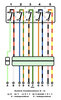
Whether there's any continuation beyond the switch-side half of the green connector will depend entirely on whoever decommissioned the bike.
There were two types; one had controls for the sidelights and headlights as Uncle Phil illustrates, and one used that switch for alternative functions (the lighting being assigned to the ignition wiring).
If your switch marked o-6-7 has no effect on your lights, you have an extra couple of choices in your wiring.
The wiring from the switchgear ends in a red and a green connector, plus a single bullet connector. The red is for ignition and lighting; green and bullet for the optional connections.
Simple diagram of the wiring for switches 1-5 is below.
Whether there's any continuation beyond the switch-side half of the green connector will depend entirely on whoever decommissioned the bike.
Thank you very helpfullOn UK bikes, switch o-1-2-3 controlled strobes and siren. o was off, 1 was front blues, 2 added siren, 3 was a non-locking (momentary) position for "yelp". 4 and 5 were rear blues pole and rear reds. They varied slightly as forces rearranged the occasional function to their preference.
There were two types; one had controls for the sidelights and headlights as Uncle Phil illustrates, and one used that switch for alternative functions (the lighting being assigned to the ignition wiring).
If your switch marked o-6-7 has no effect on your lights, you have an extra couple of choices in your wiring.
The wiring from the switchgear ends in a red and a green connector, plus a single bullet connector. The red is for ignition and lighting; green and bullet for the optional connections.
Simple diagram of the wiring for switches 1-5 is below.
Whether there's any continuation beyond the switch-side half of the green connector will depend entirely on whoever decommissioned the bike.
This was handy thank youOn UK bikes, switch o-1-2-3 controlled strobes and siren. o was off, 1 was front blues, 2 added siren, 3 was a non-locking (momentary) position for "yelp". 4 and 5 were rear blues pole and rear reds. They varied slightly as forces rearranged the occasional function to their preference.
There were two types; one had controls for the sidelights and headlights as Uncle Phil illustrates, and one used that switch for alternative functions (the lighting being assigned to the ignition wiring).
If your switch marked o-6-7 has no effect on your lights, you have an extra couple of choices in your wiring.
The wiring from the switchgear ends in a red and a green connector, plus a single bullet connector. The red is for ignition and lighting; green and bullet for the optional connections.
Simple diagram of the wiring for switches 1-5 is below.
Whether there's any continuation beyond the switch-side half of the green connector will depend entirely on whoever decommissioned the bike.
My mirrors are electric but no button actually moves them at thos stageTheo, The right hand police spec switch would have carried out the normal functions plus emergency lighting and noise. From memory the police functions should be numbered, I think 1 to 5. But that is again from memory.
Sorry but I don't understand the mirror bit.
Welcome from Northumberland, England.
Upt.
I don't believe any stock motorcycle has electric mirrors.
Pictures would be good theo. Like the man said all ST mirrors are manual.My mirrors are electric but no button actually moves them at thos stage
Upt.