Autocom Interface Issues (New Parts)

OP
OP
jfheilman

jfheilman

Site Supporter
Joined
Sep 15, 2006
Messages
460
Location
South Carolina
Bike
2007 ST1300A
jfheath, while I assumed it was out there, I had not really looked for it. It is an option. The only real reason to select it is I get to do the connection and I know the quality of the connection ;)
 
OP
OP
jfheilman

jfheilman

Site Supporter
Joined
Sep 15, 2006
Messages
460
Location
South Carolina
Bike
2007 ST1300A
Regarding quality, that is a real issue. I guess, what five years ago, the quality of these cables was pretty good. Now.....

Here is a cable advertised on Amazon. Its $9.00

https://www.amazon.com/Poyiccot-Professional-Premium-Olufsen-Systems/dp/B07VT5DJTY/ref=sr_1_4?dchild=1&keywords=7+pin+din+cable&qid=1635611277&qsid=139-5662851-8850121&sr=8-4&sres=B07DGBZNT7,B07VT5DJTY,B01CQR5L1C,B01N0DLE97,B000K67X3G,B00PZSGGZ0,B07Z68DVJW,B07VV7KHZW,B00HW7HXU4,B07HD66CN9,B07W1PKMRQ,B07VYGRF2Y,B07V7SMSM9,B07VYGGD4W,B00EHG5008,B08G1BXT4H&srpt=ELECTRONIC_CABLE

Here is a cable advertised on Newegg. Its $39.00

https://www.newegg.com/p/1B9-058H-01Z83?Item=9SIA7U1G9H4050

The pictures look the same. Seems to be the same cable but........ I suspect not.

Also, I am linking a previous discussion about just using earphones on a Autocom system using a home built adapter. I am linking the two because I believe the cable I have purchased that is hard wired only is something different since I had to include a capacitor in the building of the Doodad. in the linked article (need to verify since I don't have the schematic of the Doodad handy). This capacitor thing now has me a little concerned, since the two cables I have from Autocom (one new and one older) do not have capacitors.

https://www.st-owners.com/forums/threads/autocom-earphones-only.147145/
 
OP
OP
jfheilman

jfheilman

Site Supporter
Joined
Sep 15, 2006
Messages
460
Location
South Carolina
Bike
2007 ST1300A
Here is a picture of the schematic I found of the cable interface allowing you to use a set of headphones/earphones with the Autocom device. They are also included on the helmet loom since, I suspect, the speakers sort of need to be isolated for the headphones to work (device impedance maybe?). I also have a picture of the helmet loom with the speaker connectors and headphone jack.
 

Attachments

OP
OP
jfheilman

jfheilman

Site Supporter
Joined
Sep 15, 2006
Messages
460
Location
South Carolina
Bike
2007 ST1300A
Ok,, The 7 Pin DIN cable from New Egg came in today. It looks exactly like the one pictured in Amazon for 1/4 the price. So, Newegg sort of ripped me off. If you look closely at the cable it looks cheap and no where near as "heavy duty" as the cable from Autocom. So, using this for a replacement interface is going to be sort of a standby thing. I will probably re-use the 7 pin DIN cable that I purchased from Autocom. It is far more "sturdy" looking. The cable in the middle is the original Autocom cable.
 

Attachments

ST1100Y

Site Supporter
Joined
Dec 4, 2012
Messages
5,036
Age
59
Location
Vienna, AuSTria
Bike
ST1100Y, ST1100R
STOC #
637
... no where near as "heavy duty" as the cable from Autocom ...
Exactly the problem...
I'm looking for proper coiled leads (rubber insulation, flex screen and highly flexible strains) as well as the proper, rigid connectors since years...
One the early Autocom leads, you can slide back the rubber casing, accessing the solder-pins inside the connector, enabling DIY repair...
Later cables had glue-filled casings, the new ones you show are even molded on, hence neither are repairable...
 
OP
OP
jfheilman

jfheilman

Site Supporter
Joined
Sep 15, 2006
Messages
460
Location
South Carolina
Bike
2007 ST1300A
I shall keep looking. Somewhere they must be out there....... If not, I may just have to make my own. Again, getting the connector and cable could be an issue. But.... one never knows till one tries.
 
OP
OP
jfheilman

jfheilman

Site Supporter
Joined
Sep 15, 2006
Messages
460
Location
South Carolina
Bike
2007 ST1300A
I cut the DIN Cable today (I know $30 down the drain sort of ) and found there were seven connectors and a ground. The ground did to appear not be connected to the outer metal shield of the connector.

Did a search on line (Digikey) and found a 7 pin DIN connector there that is similar to the ones I used to build the "Doodad" for headphones only use. It is now $9.00. I don't know if it is the same "grade" as the ones I purchased before (several years ago) but..... $9.00????? Wow.
 
Last edited:
OP
OP
jfheilman

jfheilman

Site Supporter
Joined
Sep 15, 2006
Messages
460
Location
South Carolina
Bike
2007 ST1300A
While I was working with the creation of my audio interface, I was looking at the one I just purchased and fixed (had a broken wire). As I handled the Autocom one, a ground wire broke lose from its solder joint.

Turns out, it appears that to get to a "ground" connection, the manufacture simply cut a notch in the cable which exposed the braided shield and then just sort of "spot" soldered the ground connection. The image below shows this.

IMG_1160.JPG
 
OP
OP
jfheilman

jfheilman

Site Supporter
Joined
Sep 15, 2006
Messages
460
Location
South Carolina
Bike
2007 ST1300A
You probably know this already.


Those connectors are available loose and also with length of wires already attached.

I noticed a very marked change in quality in the last mic assemblies that I bought earlier this year.

A quick search for 7 pin din extension cable reveals that they can still be obtained with straight leads. You'd need to check that they were screened for audio use.
Well I sort of knew part of it but not the detail. I have "disassembled" some molex connectors before (they give you or you can buy a tool) but did not know how the JST connectors were assembled. Thanks it provides another option.

And, I did a search for the for the 7 pin din extension cables with straight leads and I could not find any in stock.. If you find a site/source, if you would let me know I would like to have a chance to buy one or two.
 
OP
OP
jfheilman

jfheilman

Site Supporter
Joined
Sep 15, 2006
Messages
460
Location
South Carolina
Bike
2007 ST1300A
From one of my previous posts

There is a plus side. The "in ear speaker loom" is wired strangely for inclusion in most helmets I have used. The connection for the mic runs forward on the loom which means it has to be folded back inside the helmet to attach to the mic. The noise sensor connection also runs forward and the noise sensor is usually wired/set in the front of th helmet which means it gets folded as well. I will correct that when I make the "in ear speaker loom".

I found out why I think. The leads in the cable (7 pin DIN) are very thin, don't know but smaller than 20 gauge. If you attach the leads for the 3/8" female audio plug to the end of the cable, there is no real way to take the strain off of this connection. In other words, you have to add something to the 7 pin DIN cable that will allow you to attach the noise sensor and mic cables to so that there is not "load" on these small wires.

If you wrap it forward and attach it to the 7 pin DIN cable, it takes all or most of the load off the smaller wires and joints.

So, I will be wiring all three cables forward. Two on top (mike and noise sensor ) and one on bottom.

Also, I got the 3.5mm male to female stereo extension cables I was going to cut and use for the earphone connection. These also came from NewEgg and are crap. There is no shield just three wires. No drain wire either. So, I will have to order some different ones. I believe one of these will be ok. Still deciding.


Still looking. Both of these say they have shields. The first one says its foil lined with a drain wire. The second one claims to have a braided shielding system. I would prefer that one....
 
OP
OP
jfheilman

jfheilman

Site Supporter
Joined
Sep 15, 2006
Messages
460
Location
South Carolina
Bike
2007 ST1300A
Ok... So I got the new cables in and they are superior in design and construction. However, they are much, much bigger. And they do have foil covering the three wires (Audio L and R and Ground) but the wires are exactly the same size as the wires in the first cables I tried. I think this new wire is much to big. I will try and find another cable maybe just drive my Best Buy or Walmart. The pictures try and compare the wires. The first picture is the two audio cables I purchased. The second picture has the Audiocom cable as a reference (the one with the broken wire).
 

Attachments

OP
OP
jfheilman

jfheilman

Site Supporter
Joined
Sep 15, 2006
Messages
460
Location
South Carolina
Bike
2007 ST1300A
I got some better 3.5mm audio cables (male to female). They had a braided ground which I liked. Cut them and began the construction. It was not really that hard but the hardest part is stripping the insulation off the very small wires without cutting the wires themselves. So here are some pictures construction. I liberally used heat shrink tubing in the construction. I tested the wires for continuity with appropriate connector but have not tested them on the Autocom unit.

The only unusual thing I did, compared to the units supplied by Autocom, was the 7 pin din connector had two extra wires. A shield and a ground to the outer shell. I wired both of those to the Pin 5 ground connection. That is the only ground connection I used. The other two grounds that are used for the "speakers" I did not connect.

Will test them in the next few days
 

Attachments

Last edited:
OP
OP
jfheilman

jfheilman

Site Supporter
Joined
Sep 15, 2006
Messages
460
Location
South Carolina
Bike
2007 ST1300A

For straight 7 pin extension lead
Says out of stock on the web page. Tried to check "Chainspeed" and they have basically nothing for the Autocom units. A real shame...... Just hope I have enough spares to keep going for the next four or five years. Chainspeed use to have a different website according to my "list". But the one I had to use was https://chainspeed.co.uk/autocom/autocom-service-parts/

Found another one and it was blank as well.

https://us-chainspeed.glopalstore.com/brands/AUTOCOM.html

Just for the record, I did log into the Autocom website (I had an account) and noted that I last ordered one in 2018 for 20 Pounds (or is it Euros?) with the new price being 25 Pounds. Actually not to bad based on other stuff's price increase.
 
OP
OP
jfheilman

jfheilman

Site Supporter
Joined
Sep 15, 2006
Messages
460
Location
South Carolina
Bike
2007 ST1300A
Update: Well they did not work. I have an older helmet interface that has connections for helmet speakers that I discarded because it had intermittent audio. I hooked it up to verify that the system still works. So, I will have to start over again. I made assumptions that things were simple and the wiring was straight forward. It appears not. I will start again, using the same parts and move forward a step at a time. I will not be grounding the 7 pin DIN connector as I did in this first try.

Step one, dissassemle and then connect only the headphones and verify that works.
Step two, wire in the microphone input jack and verify that the earphones still work and the mike works.
Step three, wire in the noise sensor input fact and verify that words and the earphone still work and the mike still works.

Unless I made a short somewhere or wired the two of them incorrectly (well I did verify they were both the same), I don't know what the problem is.

Oh, I will also do one more thing, verify the 7 Pin DIN connector pins are long enough. I believe they are since when I plugged it into the Autocom connection with the earphones in, I heard nosies.
 
OP
OP
jfheilman

jfheilman

Site Supporter
Joined
Sep 15, 2006
Messages
460
Location
South Carolina
Bike
2007 ST1300A
Did Step one in a test mode. Interesting outcome. I used the cable I had built with only the connections to the left and right speakers connected and Pin 5 which was used as ground it appeared. It did not work, no audio. Then I connected it to the left and right speaker connections and then used Pin 1 as a ground (its the ground used for in the helmet spearkers). Audio was there but louder than I expected.

I am going to have to do some more research, but...... I may have to revert to the use of the 100 UFD 10VDC caps and 68 ohm resistors I used in the original Doodad I built for earphones only.

I will recheck the use of the speaker pins and the single speaker return/ground again tomorrow and verify my results.
 

Don-STOC237

STealer
Joined
Dec 20, 2004
Messages
632
Age
76
Location
Western Nevada
Bike
Suzuki GSX1250FA-ST
STOC #
237
Pretty sure I have a couple of those cables around. My gear was all Starcom, which I think is compatible with Autocom. I have a couple of amps including on digital, BT module, some coiled cables and other stuff lying around since I converted to all wireless. If you need anything, let me know and I'll look around.
 
OP
OP
jfheilman

jfheilman

Site Supporter
Joined
Sep 15, 2006
Messages
460
Location
South Carolina
Bike
2007 ST1300A
Pretty sure I have a couple of those cables around. My gear was all Starcom, which I think is compatible with Autocom. I have a couple of amps including on digital, BT module, some coiled cables and other stuff lying around since I converted to all wireless. If you need anything, let me know and I'll look around.
Thanks Don. The main cables I would like are the straight 7 pin DIN male to female cables. And the Headset loom for in the ear speakers. Will send you a PM with my email address.
 
OP
OP
jfheilman

jfheilman

Site Supporter
Joined
Sep 15, 2006
Messages
460
Location
South Carolina
Bike
2007 ST1300A
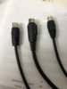
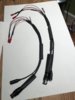
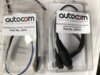
Ok.... After a couple more hours of work/testing and investigation I believe I have the final story. The original Autocom Headset Loom for in the ear speakers and in the helmet speakers and the one that was designed for just in the ear speakers and the newest one are not the same design. They are different in how they are wired. Autocom also sells a straight line 7 pin male to female cable with a little box on it to allow you to plug in in the ear speakers if you have the older headset too. This box is important.

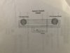
The difference is summed by the schematic below. You will note the connections for the in the ear speakers have a 68 ohm resister and a 100 uff 10VDC capacitor installed in the circuit (capacitor negative connects to the earphone jack). And you will note that the earphone ground connection goes to what I will identify as Pin 4 (if you are counting clockwise on the connector). This is the same ground used by the microphone connection. I have verified this is the same arrangement used in older versions of the headset looms (I have checked three that I have).

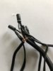
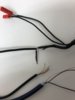
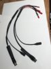
Now, the new headset loom noted in the second photo, this is part number, 2091A is different. In this design (besides the very badly done solder joints) the in the ear speaker connections ground goes to Pin 1 which is also the "Speaker Right" ground. Each Speaker (not in the ear speakers but in the helmet speakers) has its own ground. One is Pin 1 and the other is Pin 7. Again, I have verified this using that cable and manually connecting the broken solder joint wire so the audio works.

The difference between the two operations/cables is, besides the connections, is the audio from the in the ear speakers is louder using the straight through connections (no resistor or capacitor and using the speaker ground). While the louder audio might be "ok", I wonder why the designed was changed.

One reason they might have been using the the resistor capacitor combination was because they had to if you wished to use in the ear speakers with the option of also using in the helmet speakers. If would isolate the two loads from the audio source. Don't know how the impedance sensed by the Autocom unit would be affected... But...

Here is an assumption, which I cannot substantiate and that is, the impedance of my in the ear speakers is the same as the impedance of the in the helmet speakers. If that is the case, I can simply directly wire the cables audio I am building to the Pins 1, 2, and 3 (1 and 7 are ground so I could use either pin 1 or 7). But, the impemendce of the two devices bothers me.

I still have my in the helmet speakers so later today I will because their resistant (cannot do impedance in the real sense) and compare that to my earphones. Just to see.

I would prefer to use the "none component" design since it is easier to do. I do have five of the 100 Ufd caps on hand and three 68 ohm 1/4 watt resistors on hand. So, I can easily build the interface.
 

Attachments

OP
OP
jfheilman

jfheilman

Site Supporter
Joined
Sep 15, 2006
Messages
460
Location
South Carolina
Bike
2007 ST1300A
Just measured the "resistance" not "impedance" of the in the ear speakers I use and the in the helmet speakers I use. They both measure roughly 35 ohms. So...... It appears that I can, with the system I have, do a straight through wiring for the in the ear speakers not using the 68 ohm resistor and the 100uf cap.
 
Last edited:
Top Bottom