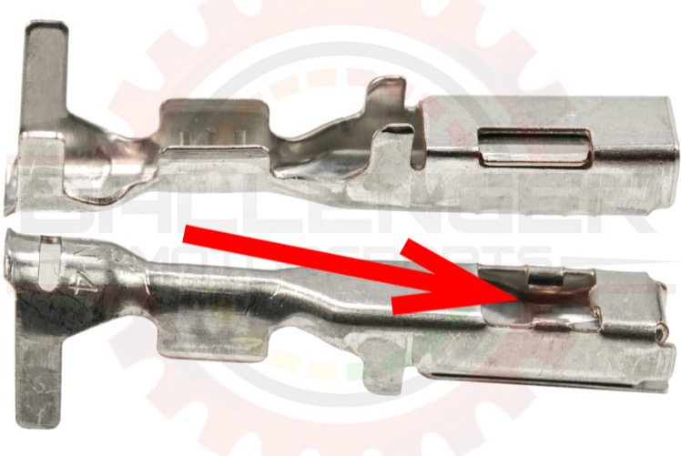
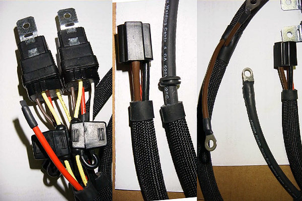
If you want to replace this connector and put new terminals on wires, you must have proper matching
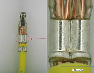
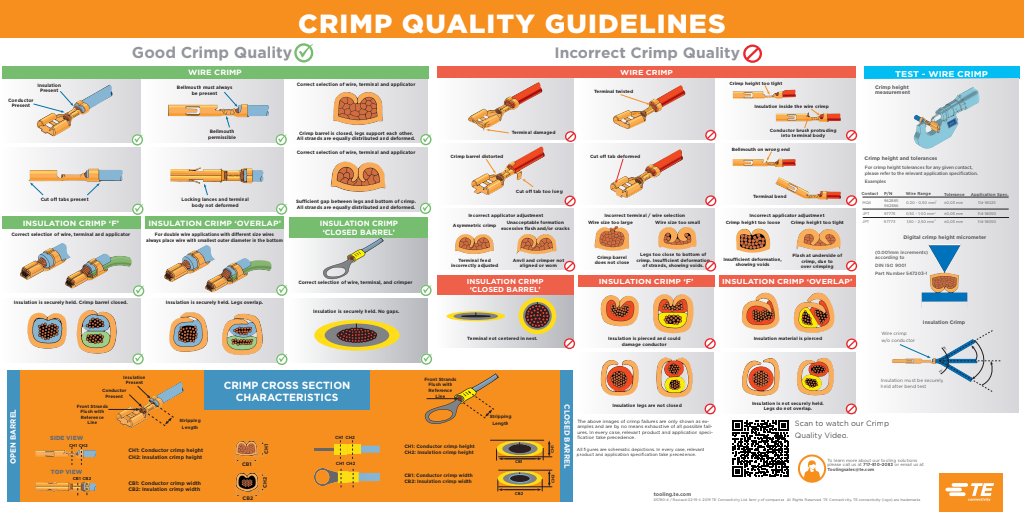
crimping system to at least match OEM specs. Not just some generic smashing crimper from auto-parts stores that just dents terminal. It needs to do dual W-crimps to squeeze OD of terminal inwards to remove air from between wire-strands to maximise contact surface area to minimise resistance for best conductivity. Also needs 2nd crimp onto insulation for strain relief.
I prefer TE/AMP Ergocrimp line of crimpers with removable crimping dies. Then when you buy terminals, vendors can provide matching die for those terminals for optimum crimping to OEM standards. A “good crimp” is not ”just any crimp”.
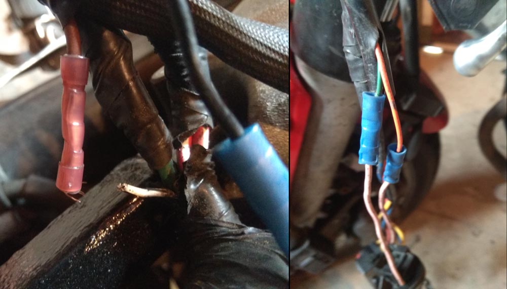
Most common wiring failures are from using generic connectors with generic crimpers. Large change in diameter with no strain-relief results in stress-risers that break wires in little time. You will never see this kind of failure with OEM wiring.
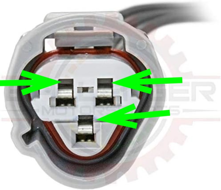
If you don’t have matching
crimping system for these Sumitomo HX/SL terminals, best to get pigtail instead. Use proper linesman/western-union knot for mechanical strength, with solder for conductivity and adhesive heat-shrink tubing for long-term corrosion resistance. It’s done this way in pro-motorsports (F1/MotoGP), military and aerospace applications for performance, reliability and durability.
Voyagers 1 & 2 are still going after 47-years using wiring standards from this manual.

drive.google.com
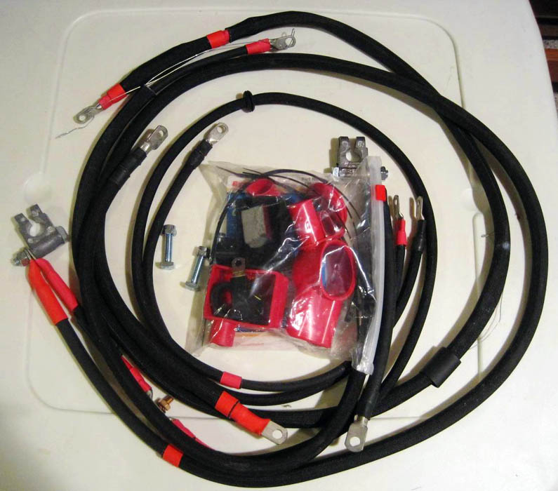
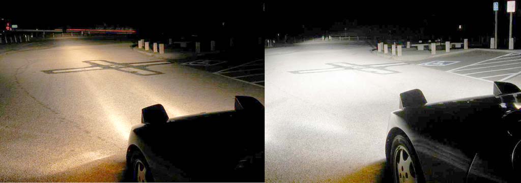
I used that manual to develop my battery cable and lighting harness upgrades for Porsches decades ago with 50-yr warranty. It’s been 30-yrs now and not single set has failed. They often appear on eBay going for double what I originally charged!
")