
Fatjock
STOC #8872
Just as an aside, I did try to put this in ST1100 Tech, which is where I thought it belongs, but I don't have permission for that. So I'm putting it where I do have permission, in case it is of some use to someone else.
This is for adding a HealTech GI Pro X-Type with the WSS to an ST1100. This is available through the distributor, Blue Monkey Motorsports. (http://shop.bluemonkeymotorsports.com/)
This is not an incredibly complex system, nor a very difficult installation, but I had my moments when doing it, and so far it has limitations. This saga includes all the pitfalls I went through, and what I did to correct them. Read it all first, and your experience should be simpler.
Let me start by saying that I have this installed, and working, but just not working as well as I would like. In the calibration section, I’ll detail how things currently are, how I got them there, and where I intend to go from here. But let me say straight off that Blue Monkey’s support has been extremely helpful and responsive, to the one question I’ve asked so far, and I could probably have used them more to get to the root cause more quickly, but where’s the fun in that? I’ll get there………but that’s for later.
Here we go.
Installation:
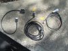
In the box you should have (going from left to right in the pic below):
As I said before, this isn’t incredibly complex. The proximity sensor detects a pulse signal from the wheel to give a pulse train corresponding to a speed signal. (This can be from the ABS ring, or as I did, the heads of the rotor bolts, as long as each is evenly spaced). The frequency of this will be proportional to the speed of the wheel, and gets compared to a revs signal from the tachometer, to determine what gear is in use.
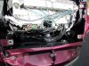
For access at the instrument binnacle you will need to remove the windshield, the garnish piece below it (black), and the two grey garnish pieces underneath it, and loosen the visor piece around the instruments.
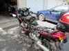
Below shows how I stripped my bike down.
The instructions that come with the unit (which I read after I had most of the install completed, of course, but more about that later) inform you that you can tap into existing ignition controlled power connections (and Scotch-Lok type connectors are provided for this), but having already added an extra fuse box, I was bound and determined to use it, so I ran my own power and ground from the fuse box to the instrument head.
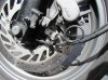
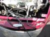
Next, I saw a likely mounting point for the sensor on the front wheel, and quickly got the sensor mounted.
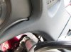
Next, I used a Dremel to grind a detent for the cable to pass through the visor, and mounted the GPI itself, running its cable back to the rear of the instruments.
So with the sensor cable run up to the instrument area, the GI unit cable there, and a power cable there, all that remained was to introduce the connecting cable and make the necessary connections.
Electrically, there are three connections required to the bike.
This is when I began to look at the instructions, and saw the “FIT THE SENSOR TO THE REAR WHEEL” note…….whoops! So if you intend to fit one of these, don’t do as I did, fit it to the rear wheel.
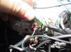
Anyway, the instructions say to tap into the tach signal, but I saw that this was being taken to a screw terminal, so I crimped on a fork terminal, and piggy-backed it at the screw terminal on the instrument.
The Green/Black wire with red crimped terminal shown in pictures below.
Updates: 11/3/15 & 11/23/15:
What I learned to finally get it operating correctly, was to switch the RPM signal source. DO NOT USE THE TACHOMETER SIGNAL for RPM input, use the Ignition Pulse Generator signal (Yellow Wire) from the ICM (LH Fairing, mounted vertically, inboard of the mirror housing).
While you can use one of the supplied connectors to splice into this wire with your Green/Black input wire, be careful doing so to ensure correct connection. Better to pull the ICM box out of the fairing, remove some insulation from the yellow wire, and solder the green/black to this to ensure proper connection. Ensure adequately insulated before refitting the ICM. (Sorry, didn't take pics when i did this)
I then connected the GI cable to its connection, the WSS sensor to its connection, and the power connections.
After that, it was tidy up, refit the Tupperware, and get ready to calibrate…….where the fun really begins.
Calibration:
Note: Carry this stage out with a warm engine.
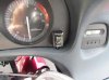
With the bike back together, and all connected up, when the ignition is turned on, the system counts down from 6 through 1, and then goes into learning mode.
Theoretically, you let the engine idle, so the system can learn the idle point. The display reads “L” flashing slowly, then faster as it learns. Once it knows where idle is, the display switches to “1” informing you to go into first gear. The instructions then tell you to keep the revs at between two to four times the idle speed, repeating this with each gear in turn.
As with the “L” at idle, the gear number will flash faster while learning. When the gear is learned, the display will display “n”, and then go to the next gear.
So, if you have the sensor on the back wheel, you can put the bike on the main stand, and carry out this process simply. I, of course, knew better, and put it on the front, so had to ride the bike at that proscribed engine revs, to calibrate.
Now, I work with Proximity sensors every day, and am familiar there set-up, so I knew the signal would be more reliable looking at a “there/not there” set-up, as opposed to “there, slightly further away” scenario. Especially since the sensing range of the sensor is not given in the instructions. Therefore, when I first set the sensor, I had it looking through the connecting arms of the front rotor.
Off I went for a calibration ride. Calibration at idle went well, into first, and off we go………the one began flashing faster as I accelerate, and when I get to around 3K revs and hold it, the display, just spins around (cursor going round the outside of the seven segment display, in sequential order). I slow down, display goes to e “2”, I try again, similar results, can’t get it to calibrate above second gear.
After several attempts with no greater success, I return to my garage. Instructions say that the spacing of pulses must be even. Where I had it could give uneven pulses. Instructions recommend looking at the head of the rotor bolts.
I realign the sensor to the rotor bolts, and off for another calibration ride. Several attempts, with similar results as before. So perhaps the bolt heads are not proud enough, and the sensor could be detecting the disc as well as the bolts. I put lock washers on the bolts to bring the heads more proud.
More calibration rides, same results.
Back to the garage, and I move the sensor from the front wheel to the rear.
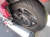
Unfortunately, when I try the calibration process, I’m getting the same result. But without having to keep an eye on the road, I’m able to observe more with what’s happening. I go through the same exercise with bolt heads, but making them more proud gives potential for interference with the caliper. So the washers come back out.
I also contact customer service to find the sensing range and frequency of the sensor.
I am told that the max frequency is 8.5 KHz, which allows the sensor to be used on ABS rings, which would be great if I had one. But with six bolts to be sensed per revolution, with the gearing of the 1100, even at 7k revs, I shouldn’t be exceeding the capability of the sensor. I also learn the max sensing range of the proximity is 1.5mm. So I adjust the sensor using feelers, to be 1.2mm from the bolt heads.
Theoretically, the bolt heads should be detected, but the disc will be too far away to be observed.
With the sensor on the rear wheel, the calibration is much simpler, so #1 tip for this is FIT THE SENSOR TO THE REAR WHEEL.
The system will, and does calibrate, but not at “between 2 and 4 times the idle speed”, it calibrates at about 1900-2000 revs (so call it 1950). My bike is set to idle at just over 1K (around 1050rpm), so calibration is occurring at 1.85 times the idle speed. But I can calibrate in all five gears.
Take the bike for a quick test ride, and the gear indicator works perfectly…………………….as long as I stay between 1000, and 2000revs. As soon as I go over 2K, the display just shows a central horizontal line.
So, the indicator serves its main use (telling me whether I’m in 3[SUP]rd[/SUP], 2[SUP]nd[/SUP], or 1[SUP]st[/SUP] if I’m stopped, or stopping at a light, looking for a neutral), but I also occasionally find myself in 4[SUP]th[/SUP], when I should be in 5[SUP]th[/SUP], so it would be useful to see the gear throughout the rev range.
I still need to use the bike, so I’ll leave it for a bit, as it is useful as it is, but this will be revisited, to try to get the calibration improved, and get it working throughout the rev range.
I'll update again when I've got further with this. But for anyone who wants to see it, I'll be at DixieSToc this weekend.
Update 11/3/15:
With the sensor on the rear wheel, and the RPM signal taken from the Ignition Pulse Gen, calibration was quick and easy, and the unit was in full operation.
So tip #2 for this is to not use the Tach signal, but the Ignition Pulse signal (Yellow Wire) from the ICM.
Not that I wanted to spoil the rest of the thread for you, but if you're looking to fit one, you may want all the correct information up-front.
Update 11/23/15:
Now have a second unit fitted to my other ST1100 as well. Installation was fairly quick and easy on this, but I was in a hurry and rushed it. Connection at the ICM wasn't good, so I had to redo it. Much easier to remove the ICM to do this.
This is one of those things that once you've done it, you'll wonder how you rode without it before..........
Now to pluck up the courage to relocate then into the instruments themselves, to make it look like they were fitted by a professional, and not a 12 year old!
This is for adding a HealTech GI Pro X-Type with the WSS to an ST1100. This is available through the distributor, Blue Monkey Motorsports. (http://shop.bluemonkeymotorsports.com/)
This is not an incredibly complex system, nor a very difficult installation, but I had my moments when doing it, and so far it has limitations. This saga includes all the pitfalls I went through, and what I did to correct them. Read it all first, and your experience should be simpler.
Let me start by saying that I have this installed, and working, but just not working as well as I would like. In the calibration section, I’ll detail how things currently are, how I got them there, and where I intend to go from here. But let me say straight off that Blue Monkey’s support has been extremely helpful and responsive, to the one question I’ve asked so far, and I could probably have used them more to get to the root cause more quickly, but where’s the fun in that? I’ll get there………but that’s for later.
Here we go.
Installation:
In the box you should have (going from left to right in the pic below):
- The Gear position Indicator, itself.
- The Wheel Speed Sensor, with mount
- And the connecting harness.
As I said before, this isn’t incredibly complex. The proximity sensor detects a pulse signal from the wheel to give a pulse train corresponding to a speed signal. (This can be from the ABS ring, or as I did, the heads of the rotor bolts, as long as each is evenly spaced). The frequency of this will be proportional to the speed of the wheel, and gets compared to a revs signal from the tachometer, to determine what gear is in use.
For access at the instrument binnacle you will need to remove the windshield, the garnish piece below it (black), and the two grey garnish pieces underneath it, and loosen the visor piece around the instruments.
Below shows how I stripped my bike down.
The instructions that come with the unit (which I read after I had most of the install completed, of course, but more about that later) inform you that you can tap into existing ignition controlled power connections (and Scotch-Lok type connectors are provided for this), but having already added an extra fuse box, I was bound and determined to use it, so I ran my own power and ground from the fuse box to the instrument head.
Next, I saw a likely mounting point for the sensor on the front wheel, and quickly got the sensor mounted.
Next, I used a Dremel to grind a detent for the cable to pass through the visor, and mounted the GPI itself, running its cable back to the rear of the instruments.
So with the sensor cable run up to the instrument area, the GI unit cable there, and a power cable there, all that remained was to introduce the connecting cable and make the necessary connections.
Electrically, there are three connections required to the bike.
- +12Vdc
- Ground
- Ignition pulse generator signal. (Yellow Wire from ICM) Ensure a good connection here to prevent calibration issues. - Updated to correct, and add more detail.
This is when I began to look at the instructions, and saw the “FIT THE SENSOR TO THE REAR WHEEL” note…….whoops! So if you intend to fit one of these, don’t do as I did, fit it to the rear wheel.
Anyway, the instructions say to tap into the tach signal, but I saw that this was being taken to a screw terminal, so I crimped on a fork terminal, and piggy-backed it at the screw terminal on the instrument.
The Green/Black wire with red crimped terminal shown in pictures below.
Updates: 11/3/15 & 11/23/15:
What I learned to finally get it operating correctly, was to switch the RPM signal source. DO NOT USE THE TACHOMETER SIGNAL for RPM input, use the Ignition Pulse Generator signal (Yellow Wire) from the ICM (LH Fairing, mounted vertically, inboard of the mirror housing).
While you can use one of the supplied connectors to splice into this wire with your Green/Black input wire, be careful doing so to ensure correct connection. Better to pull the ICM box out of the fairing, remove some insulation from the yellow wire, and solder the green/black to this to ensure proper connection. Ensure adequately insulated before refitting the ICM. (Sorry, didn't take pics when i did this)
I then connected the GI cable to its connection, the WSS sensor to its connection, and the power connections.
After that, it was tidy up, refit the Tupperware, and get ready to calibrate…….where the fun really begins.
Calibration:
Note: Carry this stage out with a warm engine.
With the bike back together, and all connected up, when the ignition is turned on, the system counts down from 6 through 1, and then goes into learning mode.
Theoretically, you let the engine idle, so the system can learn the idle point. The display reads “L” flashing slowly, then faster as it learns. Once it knows where idle is, the display switches to “1” informing you to go into first gear. The instructions then tell you to keep the revs at between two to four times the idle speed, repeating this with each gear in turn.
As with the “L” at idle, the gear number will flash faster while learning. When the gear is learned, the display will display “n”, and then go to the next gear.
So, if you have the sensor on the back wheel, you can put the bike on the main stand, and carry out this process simply. I, of course, knew better, and put it on the front, so had to ride the bike at that proscribed engine revs, to calibrate.
Now, I work with Proximity sensors every day, and am familiar there set-up, so I knew the signal would be more reliable looking at a “there/not there” set-up, as opposed to “there, slightly further away” scenario. Especially since the sensing range of the sensor is not given in the instructions. Therefore, when I first set the sensor, I had it looking through the connecting arms of the front rotor.
Off I went for a calibration ride. Calibration at idle went well, into first, and off we go………the one began flashing faster as I accelerate, and when I get to around 3K revs and hold it, the display, just spins around (cursor going round the outside of the seven segment display, in sequential order). I slow down, display goes to e “2”, I try again, similar results, can’t get it to calibrate above second gear.
After several attempts with no greater success, I return to my garage. Instructions say that the spacing of pulses must be even. Where I had it could give uneven pulses. Instructions recommend looking at the head of the rotor bolts.
I realign the sensor to the rotor bolts, and off for another calibration ride. Several attempts, with similar results as before. So perhaps the bolt heads are not proud enough, and the sensor could be detecting the disc as well as the bolts. I put lock washers on the bolts to bring the heads more proud.
More calibration rides, same results.
Back to the garage, and I move the sensor from the front wheel to the rear.
Unfortunately, when I try the calibration process, I’m getting the same result. But without having to keep an eye on the road, I’m able to observe more with what’s happening. I go through the same exercise with bolt heads, but making them more proud gives potential for interference with the caliper. So the washers come back out.
I also contact customer service to find the sensing range and frequency of the sensor.
I am told that the max frequency is 8.5 KHz, which allows the sensor to be used on ABS rings, which would be great if I had one. But with six bolts to be sensed per revolution, with the gearing of the 1100, even at 7k revs, I shouldn’t be exceeding the capability of the sensor. I also learn the max sensing range of the proximity is 1.5mm. So I adjust the sensor using feelers, to be 1.2mm from the bolt heads.
Theoretically, the bolt heads should be detected, but the disc will be too far away to be observed.
With the sensor on the rear wheel, the calibration is much simpler, so #1 tip for this is FIT THE SENSOR TO THE REAR WHEEL.
The system will, and does calibrate, but not at “between 2 and 4 times the idle speed”, it calibrates at about 1900-2000 revs (so call it 1950). My bike is set to idle at just over 1K (around 1050rpm), so calibration is occurring at 1.85 times the idle speed. But I can calibrate in all five gears.
Take the bike for a quick test ride, and the gear indicator works perfectly…………………….as long as I stay between 1000, and 2000revs. As soon as I go over 2K, the display just shows a central horizontal line.
So, the indicator serves its main use (telling me whether I’m in 3[SUP]rd[/SUP], 2[SUP]nd[/SUP], or 1[SUP]st[/SUP] if I’m stopped, or stopping at a light, looking for a neutral), but I also occasionally find myself in 4[SUP]th[/SUP], when I should be in 5[SUP]th[/SUP], so it would be useful to see the gear throughout the rev range.
I still need to use the bike, so I’ll leave it for a bit, as it is useful as it is, but this will be revisited, to try to get the calibration improved, and get it working throughout the rev range.
I'll update again when I've got further with this. But for anyone who wants to see it, I'll be at DixieSToc this weekend.
Update 11/3/15:
With the sensor on the rear wheel, and the RPM signal taken from the Ignition Pulse Gen, calibration was quick and easy, and the unit was in full operation.
So tip #2 for this is to not use the Tach signal, but the Ignition Pulse signal (Yellow Wire) from the ICM.
Not that I wanted to spoil the rest of the thread for you, but if you're looking to fit one, you may want all the correct information up-front.
Update 11/23/15:
Now have a second unit fitted to my other ST1100 as well. Installation was fairly quick and easy on this, but I was in a hurry and rushed it. Connection at the ICM wasn't good, so I had to redo it. Much easier to remove the ICM to do this.
This is one of those things that once you've done it, you'll wonder how you rode without it before..........
Now to pluck up the courage to relocate then into the instruments themselves, to make it look like they were fitted by a professional, and not a 12 year old!
Last edited: