See if this works
Attachments
-
 155.6 KB Views: 31

Confirmed... Most useful function of that red connector is for gear-indicators.
Confirmed
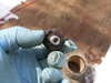
After 2 feet of snow, I finally got the chance to go a little deeper in the bike and remove the cooling pump. Underneath the cooling pump is this little guy. Buried in mouse poo. Plus another wiring harness to replace. This is the one that has the 2 knock sensors 10 pin grey plug on the right side of the bike. Any idea what the part number is for the wiring harness and this little sensor?? This sensor doesn't really look damaged. Just dirty, but its buried so deep underneath I think Ill just replace it. Im pretty sure this will clean up 1 of the 2 FI codes....The other is The IAT switch. No brainer.You jumpered crank pulse sensor? Why?
Don’t make any changes to system to troubleshoot, you’ll fry something and/or introduce additional errors into system. Passive measurements only and let numbers tell you exactly what’s wrong and how to fix it.
It’s like going to doctor, “We think your tiredness is because of weak heart. Let’s swap in another one to see if you feel better!” Nah, first up is always series of tests to gather numbers like BP, RHR, BMI, A1C, BUN, etc. Then based upon numbers, fault is identified 1st, before any corrective actions are taken.
These are not reed-switches like old-style speedos. They’re VR - variable reluctance sensors that have voice-coil over magnet and outputs an analogue waveform when trigger teeth flies past them.

Looks like this on oscilloscope:

ECU uses combination of cam & crank VR sensors to determine engine position and speed.


Codes 18 & 19 are for following conditions on CMP/CKP sensors:
1. loose or poor contact on cam/ignition pulse generator (high ohms out of range)
2. open or short-circuit in cam/ignition pulse generator (infinite ohms/OL or zero ohms)
3. faulty cam/ignition pulse generator (improper signal)
By jumpering crank sensor connector, you’ve created fault #2 in circuit on top of any existing errors.
By this, he means pull out meter, follow procedure in manual and measure.
1. Since this isn't a switch, sensors have coils with measurable impedance. Measure resistance of sensor at its connector, should be 400-600 ohms.
2. Measure sensor resistance again at ECM connector. This verifies wiring is OK between sensor and ECM. Doesn't matter one bit if sensor is perfectly OK if signal never makes it to ECM
3. Measure resistance of each sensor-wire to chassis-ground to verify it's not frayed and shorted to metal nearby. Some of these wires run across very hot metal and may have contacted something to melt insulation off.
4. measure peak VAC output of sensor at ECM connector when cranking. Should be > 0,7 VAC
These measurements being out-of-spec are possible causes behind error #18 & 19. When resistance-measurement of sensor is outside of normal range, ECM throws code. Or if signal doesn't meet minimum output levels.

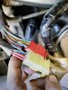
What's this little red plug guy? W diagram says service connector. Anybody have any luck troubleshooting the ECM with this plug? Notice the plastic in the back. Thats how much the mice ate away at the plastic............Also, is there a quick reference guide on the different connector plug names. I split open a double female terminal with a fluke meter. Thanks again.
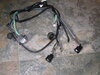
So, at this point I have replaced the Main wire harness, throttle body harness and now I'm replacing the pulse gen harness. While I'm at it, the alt needs cleaning, and you can see from the photos that need some elbow grease on the contacts. I'm certain this will produce spark. If not at least clear the 18 code......Confirmed