I killed my Turn Signals and Flashers

Sadlsor

Site Supporter
Joined
Jan 15, 2020
Messages
4,290
Age
66
Location
Birmingham, Alabama
Bike
2008 ST1300A
STOC #
9065
My turn signals and 4-way flashers are no longer working; I must have did somebody wrong!
Background: added trailer isolation harness for trailer wiring, powered by the rear taillight (not brake light.) This was done with the help of an electrician and rider buddy who has done lots of work on bikes. I got my trailer way far away, and ALL lights, signals, and flashers worked with the trailer attached, and rode home with no issues.
Weeks later, I added the quartet harness to power my Zumo XT, using a switched circuit. The GPS isn't powering on with bike power.
Also added Warm N Safe wiring - direct to battery - and that works fine, for gloves and jacket.
All other electrics working otherwise.
Today I finally had some time to explore, checked the main fuse on the right-hand side and it's good. Fusible link is intact.
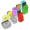
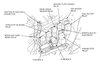
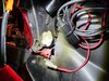
There's a black box near the relays on the left side, and I think one of the mini fuses in the service manual said Turn Signal or Turn Signal Relay, I don't recall now, but it's a 10-amp and it was solid.
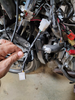
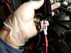
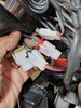
Found the turn signal relay on the left side, and called Larry because I thought I had to remove the rubber cover to test it. He said NO! so I didn't destroy it. I plugged the female side- the wired, non-relay white connector - into a couple of the other relays nearby and started the bike, but still no signals or flashers. I tried the turn signal relay on a couple of other connectors but not sure which ones; two were outboard - away from the center of the bike - of the turn signal relay. Still no flashers, but the bike started and ran, with headlights, hi-beam, horn and brake lights all working.
When I try to use the turn signals there is no audible clicking noise, and the front amber bulb on that side goes dark. Both sides do that.
I'm floundering, and am just guessing, doing plug-and-play, er, -pray.
2008 ST1300-A (ABS) with 28K and change, tires inflated to recommended pressure but I'm late with an oil change, and the bike is dirty but the tank is full of petrol.
I rode the bike today for a restaurant job nearby, and to get a car battery at Costco.
My left arm was busy in lieu of electric blinking bulbs to signal my intention at intersections. Do you think car drivers recognize the manual right hand turn signal?
Anyone who can help give me a sense of direction to track this down and repair it, would be appreciated. Surely it's something stupid-simple?
 

Andrew Shadow

Site Supporter
Joined
Jan 28, 2012
Messages
5,122
Location
Montreal
Bike
2009 ST1300A9
Did the turn signals stop working after you connected the Zumo XT?
If so, what wires did you connect the Zumo XT to?

The quartet harness includes wires connected to the turn signal circuits. If the turn signals stopped working when the XT was wired in, I would look there.
 

STRider

Site Supporter
Joined
Mar 17, 2020
Messages
1,114
Age
64
Location
Oregon
Bike
2012 ST1300A
STOC #
50
If you plugged the Zumo into one of the quartet harness (QH) connectors, do the signals and flashers work if you disconnect the Zumo?

Did you use one of the three-pin connectors or the nine-pin connector for the Zumo's power? As @Andrew Shadow mentions, the main nine-pin female connector on the bike which the QH plugs into also has right (light blue) and left (orange) turn signal wires in it. The nine-pin connector on the QH pass those circuits through to another nine-pin connector which replicates what's on the bike's harness while breaking out three three-pin connectors for the accessories - heated grips, accessory light plug power outlet and audio (I believe). If you plugged the Zumo into the nine-pin connector on the QH you may have connected to the wrong circuit(s).


You can see the nine-pin connector of the QH behind the thick black wire bundle just above my hand along with the three other three-pin connectors of the QH.

1678088736027.png
 

jfheath

John Heath
Site Supporter
Joined
Mar 18, 2006
Messages
2,834
Age
70
Location
Ilkley, W Yorkshire, UK
Bike
2013 ST1300 A9
2024 Miles
000679
STOC #
2570
I think that the turn signal 'relay' is a solid state device. It doesn't make a noise. It has a different product code from all of the other relays, as it does a different job. It has to turn on and off pairs of indicator bulbs. Im not sure how it copes with hazard lights. I'll find out when I can get to my magnifying glass and the full circuit diagram.

1678114854543.png

What info I do have at hand shows shows a 15A fuse for Turn, Acc. Fuse F. Which would be correct - 4 hazard lights at 21w each is around 7A at 12v. Leaves enough for the quartet harness heated grips.

If you have a 3 pin connector to fit the 3 on the quartet harness, try your gps in any of the other two that you haven't tried. One of the three connectors provides power that comes on with ignition, one with accessories. These two have only two wires connected.
Only one connector has three wires - the black one in the images below, but your harness may vary. If you use this one, the gps may always be on. The 3 quartet connectors get their power from three different fuses.

For that 3P connector, the earth wire is aways closest to the locating groove / ridge in the side of the housing - on the left when seen as shown int he photos below.

Since I have seen information that suggests that the colours used are not the same from one harness to the next, it would be a good idea to check the voltage of each pin for yourself. The images below show the connector with the groove and the earth wire on the left.
1678106497955.png
1678106521604.png
1678106532809.png
 
Last edited:

Hound

Cave Canem
Joined
Nov 18, 2007
Messages
1,178
Age
63
Location
Wales, UK
Bike
2004 ST1300PA
STOC #
4607
On my bike the turn signal/hazards/acc fuse is a 15A - "F" in the fusebox.

I changed my relay many years ago to one that can handle LED bulbs without hyper-flashing, and also operate incandescent if required. The relay is a simple one with only two connections. It's hidden away a bit at the back of the other relays, though.

relays.jpg

I'd send you my old relay which I have doubtless squirrelled away somewhere, but I haven't a clue where it is. Here's an inexpensive one on fleaBay:


This one's cheaper, says it's for a Yamaha but part number is the same (FE246BH).

 
Last edited:
OP
OP
Sadlsor

Sadlsor

Site Supporter
Joined
Jan 15, 2020
Messages
4,290
Age
66
Location
Birmingham, Alabama
Bike
2008 ST1300A
STOC #
9065
On Jan 15 this year, I connected the Zumo XT to the RED 3-pin connector on the quartet harness; IIRC I was going for SWITCHED Power AND ACCESSORY Power. I "think" that's why I selected that one, after reading the pinouts for the harness multiple times. After posting this, I am going to unplug the GPS and report back...

Zumo XT to red q harness.jpg
 

Obo

Joined
Oct 22, 2019
Messages
4,296
Location
East Coast Canada
Bike
'03 ST1300A
0. you said you checked fuses. If not, do it again.

1. check a bulb. The front turn signals are easiest. If the bulb is bad, replace and re-check. If it works then check the other front. If it's bad, you've likely blown them all and need to find "why."

2. check the relay under the left panel. The relay does both turns and 4 ways. The power comes into the handlebar switch from the relay and if you use the direction signal switch it goes one way. Use the 4 ways and it goes to both. (sort of like a jumper.)

3. check the switch assembly on the handlebar.

4. check the wiring connectors under the Tupperware around the quartet harness. Look for loose connectors, wires etc.
 
OP
OP
Sadlsor

Sadlsor

Site Supporter
Joined
Jan 15, 2020
Messages
4,290
Age
66
Location
Birmingham, Alabama
Bike
2008 ST1300A
STOC #
9065
I clipped loose my pretty, tidy, and ineffective wiring and disconnected my white connector from the red 3-pin connector at the quartet harness.
No turn signals, no flashers, no joy with the key on. Engine not started... should go blinky-blink without it running.
My wired white connector at the bottom center, black shiny quartet harness up top-center in the picture.
When I connected the quartet harness, I confirmed I had power to two of the pins in the 3-pin red connector, one wire with key on and another wire with key in ACC positions, and no voltage with the key off.
Now I must leave for work and dog walk, not in that order, so I'll check in later and review your suggestions.
Thanks to all VERY MUCH; I'm sure you'll steer me to this easy fix that is apparently beyond me...

GPS connector to q-harness.jpg
 

jfheath

John Heath
Site Supporter
Joined
Mar 18, 2006
Messages
2,834
Age
70
Location
Ilkley, W Yorkshire, UK
Bike
2013 ST1300 A9
2024 Miles
000679
STOC #
2570
When I connected the quartet harness, I confirmed I had power to two of the pins in the 3-pin red connector, one wire with key on and another wire with key in ACC positions, and no voltage with the key off.
Your quartet harness is different from mine then - for me it is the black connector that has the 3 pins wired. My red connector has 2 pins wired as shown a few posts back.
Which pins did you wire in your white connector? The two outside ones ? I don't need an answer - but you do. Because if it is the outer one, and it is connected to the 3P connector which has 3 wires connected, then you may have wired your GPS to the 'always on' feed. - which comes from a different fuse - Fuse J in my case, which also powers the clock.. That would be the case if your wiring matches my pics a few posts back.

The colours of the actual wires should be consistent, even if the colours of the connectors isn't.

Nb the connections that come on with accessories, also come on with ignition - which is what you would want for your GPS. There Q harness has on lead (white in my photos) that has a connection which comes on with ignition, but not with accessories. That would be for heated grips. The accessories position is designed to turn on only a minimum number of components to keep the current draw as low as possible.

I did away with the quartet harness and made my own version with a 9 pin connector and leads that go exactly where I want them to be - so that I didn't have all of that wiring bundled up where the harness is supposed to fit.
 

Hound

Cave Canem
Joined
Nov 18, 2007
Messages
1,178
Age
63
Location
Wales, UK
Bike
2004 ST1300PA
STOC #
4607
This thread started by Joe (Mellow) has some helpful info.


My phone didn't show all of John's very useful content a few posts up, so apologies for duplicating info. :rolleyes:
 
Last edited:

STRider

Site Supporter
Joined
Mar 17, 2020
Messages
1,114
Age
64
Location
Oregon
Bike
2012 ST1300A
STOC #
50
Just for reference I found a different photo of the business end of my quartet harness. As per John's post above, you can see my black connector has three pins. In this photo I had just attached an empty nine-pin male connector to the QH along with my accessories attached to the three three-pin connectors. I hope this helps. (I took this photo for exactly this purpose!)

Full disclosure, I bought mine from used from CMS in the Netherlands when there were none to be found in stock in the USA. If there's indeed a difference between those sold in Europe vs. North America, mine's likely a European version.


20221230_211103.jpg
 

Andrew Shadow

Site Supporter
Joined
Jan 28, 2012
Messages
5,122
Location
Montreal
Bike
2009 ST1300A9
If there's indeed a difference between those sold in Europe vs. North America, mine's likely a European version.
Mine was ordered directly from Honda Canada through a Canadian Honda dealer, so it is whatever was distributed to North America and is the same as yours.
As far as I remember there was only one quartet harness P/N, so it would be the same everywhere.

The Quartet Harness 3-Pin Black Connector has wires in all three positions.
The Quartet Harness 3-Pin Red Connector has wires in the two outer positions only.
The Quartet Harness 3-Pin Natural/White Connector has wires in the two outer positions only.
 

Andrew Shadow

Site Supporter
Joined
Jan 28, 2012
Messages
5,122
Location
Montreal
Bike
2009 ST1300A9
More than once I could not see that a fuse was blown, the smaller the harder.
It is much more reliable to test fuses using a 12V test light, even better than using a continuity tester/OHM meter.
With the fuse installed and the ignition switch in whatever position is required to supply power to the fuse being tested, probe both of the exposed metal on either side of the fuse with the test light tip while the alligator clip is connected to a known good ground. If the test light does not illuminate when touched to both sides of the fuse, or not at all, there is something wrong.
 

STRider

Site Supporter
Joined
Mar 17, 2020
Messages
1,114
Age
64
Location
Oregon
Bike
2012 ST1300A
STOC #
50
Last edited:
Top Bottom