- Joined
- May 27, 2021
- Messages
- 1,027
- Age
- 63
- Location
- Coquitlam British Columbia Canada
- Bike
- 2009 ST1300
Does this seem right? A mix of what I've found available through the site and my own beliefs.
Another Linked Braking System Interpretation
Incomplete
The following represents another attempt to understand, assemble, describe and explain the workings of the ST Linked Braking System
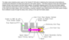
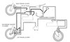
When the brake pedal is depressed, brake fluid pressure from the rear master cylinder is applied to two elements; the rear brake caliper center piston and the inlet of the two stage delay valve.
The full brake fluid pressure potential of the rear master cylinder is applied to the rear caliper.
The delay valve which receives fluid from the rear master cylinder has two outlet ports. The first port connects to a tee which branches out to two elements; the front left caliper center piston and the secondary master cylinder inlet. The second port connects to the front right caliper center piston.
The delay valve allows fluid pressure from the rear master cylinder to transfer through a restrictor to the front left-caliper piston and the SMC inlet while initially preventing fluid pressure from acting on the front right caliper center piston until the fluid pressure reaches a specifically determined value.
The effect of rear brake application to this point would be immediate application of the rear center piston and gradual application of the front left center piston [via the restrictor]. In other words, a partial depression and holding of the brake pedal would affect immediate moderate force on the rear caliper, and a gradually increasing force on the front left caliper as fluid crosses the restrictor. Further, if the rear pedal position and pressure is maintained the movement of fluid through the restrictor will proportionately deplete fluid from the circuit causing the rear centre piston to retract.
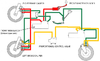
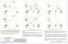
When the brake pedal is initially applied, fluid pressure moves the spool against the spool valve [compressing the spool secondary spring], this action seals the delay valve secondary chamber, preventing any fluid from passing to the right front brake caliper. At this time all fluid pressure passes through a flow restrictor to the left-front brake caliper.
As the application of the brake pedal is increased, fluid pressure will move the spool and the spool valve as it overcomes the spool primary spring, allowing fluid to pass to the right-hand brake caliper. At this time all fluid pressure is equalized to all three brake calipers.
Another Linked Braking System Interpretation
Incomplete
The following represents another attempt to understand, assemble, describe and explain the workings of the ST Linked Braking System
When the brake pedal is depressed, brake fluid pressure from the rear master cylinder is applied to two elements; the rear brake caliper center piston and the inlet of the two stage delay valve.
The full brake fluid pressure potential of the rear master cylinder is applied to the rear caliper.
The delay valve which receives fluid from the rear master cylinder has two outlet ports. The first port connects to a tee which branches out to two elements; the front left caliper center piston and the secondary master cylinder inlet. The second port connects to the front right caliper center piston.
The delay valve allows fluid pressure from the rear master cylinder to transfer through a restrictor to the front left-caliper piston and the SMC inlet while initially preventing fluid pressure from acting on the front right caliper center piston until the fluid pressure reaches a specifically determined value.
The effect of rear brake application to this point would be immediate application of the rear center piston and gradual application of the front left center piston [via the restrictor]. In other words, a partial depression and holding of the brake pedal would affect immediate moderate force on the rear caliper, and a gradually increasing force on the front left caliper as fluid crosses the restrictor. Further, if the rear pedal position and pressure is maintained the movement of fluid through the restrictor will proportionately deplete fluid from the circuit causing the rear centre piston to retract.
When the brake pedal is initially applied, fluid pressure moves the spool against the spool valve [compressing the spool secondary spring], this action seals the delay valve secondary chamber, preventing any fluid from passing to the right front brake caliper. At this time all fluid pressure passes through a flow restrictor to the left-front brake caliper.
As the application of the brake pedal is increased, fluid pressure will move the spool and the spool valve as it overcomes the spool primary spring, allowing fluid to pass to the right-hand brake caliper. At this time all fluid pressure is equalized to all three brake calipers.
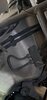

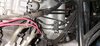
") The top line comes from the front m/c, into that top 'clamp' (just a fancy host mount), along the top steel line and into the front 'inboard' ABS connection. Then out from the front 'outboard' ABS line, through the lower steel line and clamp, then back into flexi where it drops down under the triples down to both front calipers (and activates the outer pistons)
The top line comes from the front m/c, into that top 'clamp' (just a fancy host mount), along the top steel line and into the front 'inboard' ABS connection. Then out from the front 'outboard' ABS line, through the lower steel line and clamp, then back into flexi where it drops down under the triples down to both front calipers (and activates the outer pistons)