Quartet Harness - Black connector - Advmonster Model 20 lights

90210brandon

Be a Zero
Joined
Oct 3, 2013
Messages
101
Location
Vancouver
Bike
07 Silver ST13
STOC #
8998
Given the quartet harness is made for farkling, do you believe, like I do that the black connector will work for installing the above-mentioned?

The best wiring diagram I can find for the lights are here...

Screen Shot 2020-12-27 at 7.32.29 PM.png
 

jfheath

John Heath
Site Supporter
Joined
Mar 18, 2006
Messages
2,859
Age
70
Location
Ilkley, W Yorkshire, UK
Bike
2013 ST1300 A9
2024 Miles
000679
STOC #
2570
The Black connector from the Quartet Harness has three terminals
One is Grn (earth)
The centre one is LGrn/Bk which comes on when the key is turned to Ignition or accessories.
The other outside terminal (Red/Grn) is always live.

The white and red connectors both have no centre pin. The other two pins are live and earth. These are both turned on by the ignition key:
White connector is live only when the key is turned to ignition (not when turned to accessories).
Red connector is live when the key is turned to either accessories or ignition.

If you are just wanting to turn on the relay from the connector, then yes - there is plenty of capacity for you to do that. I would use the earth and live from the white connector for that.

Whether you can power your lights from the connectors depends on the power consumption of the lights.

I estimate that the cable and fuses can support another 7A (red and white connectors). The always on terminal can probably support another 10A.

So for lights always on when the ignition is on, you could use the centre pin and earth to turn on the relay and use the red/grn outside pin and earth to provide the always on power to the relay. But your lights must never draw more than 10 amps to do it this way.

Or - if the lights don't draw more than 7A total, you could just power them from the white connector.

Please double check my figures for yourself. I'm pretty sure they are right - but I have been 'right' before. Always better to check information provided by some unknown entity on the internet.

I think I'll write this up properly - I'm using my scribbled notes from a couple of weeks ago when I was planning a new accessory harness.
 
Joined
Sep 4, 2013
Messages
8,166
Location
Cleveland
Bike
2010 ST1300
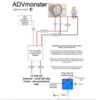
Careful there, please check to see what fuses control the quartet harness' various plugs. I have not checked, because I am using them for very low powered applications so I did not look for the specifics. I've read here that the various connectors are powered by 3 and 5 amp fuses - going by memory so I might be wrong. As @jfheath said, the connectors might not support the load of your lights but they will support a switching relay - one that uses power for the lights from another source (you have shown that as a fused circuit from the battery). Just because a fuse is of sufficient size to power your lights, does not mean that is an all clear sign. You need to see what other loads (lights, etc.) are protected by that fuse. Honda's engineers designed their wiring system to carry juice to the various accessories very carefully. If you look closely, many wires are very small - designed for the small loads they serve. Tapping into them can lead to problems. Those engineers did not design this bike for us to play with the wiring system on a lark - they served their needs, not ours or future owners'. I admit to being surprised at what some guys get away with - and that is testimony to the engineering safety factors built into many items, not their own knowledge of what they are doing.
 

Obo

Joined
Oct 22, 2019
Messages
4,289
Location
East Coast Canada
Bike
'03 ST1300A
I think I'd be temped to run wires back to the battery and put a relay in there from a localized switched source neat it and not tap into the harness (unless you specifically have the quartet harness already or want to make one.)
 

Andrew Shadow

Site Supporter
Joined
Jan 28, 2012
Messages
5,103
Location
Montreal
Bike
2009 ST1300A9
The quartet wiring harness black connector has the following capacity;

Green wire is ground/earth.
Red/green wire is constant 12 V + connected to 10 amp fuse J (ABS) or H (non ABS).
Light green/black wire is switched 12 V + with the ignition switch in the run and accessories position. It is connected to 15 A fuse F (ABS) or E (non ABS).

I compiled the above from various posts on this site but have not checked it against the wiring diagram or my bike. If you have the quartet harness installed the above is easy to verify.
 

jfheath

John Heath
Site Supporter
Joined
Mar 18, 2006
Messages
2,859
Age
70
Location
Ilkley, W Yorkshire, UK
Bike
2013 ST1300 A9
2024 Miles
000679
STOC #
2570
Here you are - These figures are taken from the circuit diagram for an ST1300 A9

Please note that the connections to fuses for the standard non-ABS model are different from the information given here.

The groove in the side of the connectors - visible on the left side in the black and the white photos - always seems to be the one next to the green earth lead. That is true for all of the 2P and 3P connectors I have inspected.


Quartet Black Connector.jpg

Quartet Red Connector.jpg

Quartet White Connector.jpg
 
Last edited:
OP
OP
90210brandon

90210brandon

Be a Zero
Joined
Oct 3, 2013
Messages
101
Location
Vancouver
Bike
07 Silver ST13
STOC #
8998
Thanks everybody for your imput. You have helped a lot. I'll do some more research and check my calculation over this winter. I'll let you know how it goes.

I have already plugged into the clear connector with replacement heated grips (non-Honda) and used the red connector for a digital voltage readout (I understand that it is not truly representative of the voltage at the battery but that was never the point of its installation).
 
Joined
Aug 21, 2018
Messages
6,756
Location
Richmond, VA
Bike
'01 & '96 ST1100s
STOC #
9007
I have already plugged into the clear connector with replacement heated grips (non-Honda) and used the red connector for a digital voltage readout (I understand that it is not truly representative of the voltage at the battery but that was never the point of its installation).
A volt meter uses so little current that it will not cause voltage drop. It will, however show any drop caused by other loads sharing the same pathway.
 

ST1100Y

Site Supporter
Joined
Dec 4, 2012
Messages
5,037
Age
59
Location
Vienna, AuSTria
Bike
ST1100Y, ST1100R
STOC #
637
Now if anyone can tell me what the 'Pass' feature is on Fuse C...
EC spec feature to flick high beams...
The HIGH switch-plate on LHS switch-pod can be dipped forward (non latching) sending (intermittent) voltage to the high beams for signaling/warning purpose...

(IMHO quite unpractical... unless you'll grow like a second thumb out the top of your left palm of course...
I prefer the old style switch setup one can easily operate with the left index finger... while grabbing the clutch and having the thumb on the horn button, common in distress situations...)
 
Joined
Aug 21, 2018
Messages
6,756
Location
Richmond, VA
Bike
'01 & '96 ST1100s
STOC #
9007
The pass button energized the headlight high-beam relay, not the bulb directly, so the current is minimal.
 

ST Gui

240Robert
Site Supporter
Joined
Sep 12, 2011
Messages
9,268
Location
SF-Oakland CA
Bike
ST1300, 2010
The pass button energized the headlight high-beam relay, not the bulb directly, so the current is minimal.
This is what I'd expect if only to minimize wear and tear on the Pass button unlike the horn button which doesn't use a relay in the factory setup IIRC. I'm not sure the meeper draws much more current than a single .02W LED. (No I'm not serious.)
 

jfheath

John Heath
Site Supporter
Joined
Mar 18, 2006
Messages
2,859
Age
70
Location
Ilkley, W Yorkshire, UK
Bike
2013 ST1300 A9
2024 Miles
000679
STOC #
2570
The pass button energized the headlight high-beam relay, not the bulb directly, so the current is minimal.
Thanks for the comment - The ST1300 does something different though.

I've deleted my original replies above as my suggestion turned out to be wrong, and it was getting away from the subject of this thread about the quartet harness. I knew that the right hand bulb is switched directly and only the left hand bulb is switched by relays. I have just worked out how the Pass switch functions.

It didn't help that my 2004 Honda service manual has a few components of this circuit are drawn and/or labelled differently from the wiring on my ST1300A9. I finally got it worked out. I've put it altogether in a new post here:

 
Last edited:
Top Bottom