Gus1300
Site Supporter
Got my '04 buttoned back up recently from the Race Tech upgrade I bought back in March. In case anyone is interested, this was the first time into the forks, steering head, and valve check for me. Also first time having the front wheel off myself. Pretty straightforward but I'll highlight a few areas where the common sense side of the house didn't quite prevail. As always, recommend getting the service manual and becoming familiar with the pages/pictures that deal with the area of interest for your project at the time. Some of the pictures are basic, but I find it helps sometimes to know what to expect if you haven't 'been there, done that' yet so pictures as things came apart is where I'll start things off:
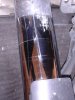
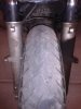
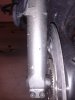
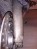
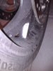
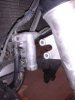
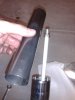
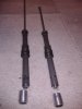
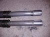
Here's a comparison of the left and right forks (as viewed from the front), which is why I decided to go ahead and do this swap now. Started to see some fluid on the left fork and wasn't sure how much was still inside or what shape it was in. The wheel was getting coated as well. All indications that there was something amiss. No, I didn't use the 35mm film trick or the commercial product for helping to clear the seals. In my mind, if the fluid was getting that high up, it was time to put my well earned money (and well spent on the RC kit!) to good use.
The fender comes off fairly straightforward. The reflector clips have to be loosened for the bolt heads to clear, or removed entirely. I just loosened them. While it was off I put on my STuffSTopper...great product, went on perfect and so far has done the job...highly recommended if you're out of farkle ideas.
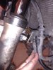
I removed the right side delay valve and crossover lines first; when it all went together, I think it would be easier in sequence to do the left brake hose clamp first but the manual says otherwise. Just be careful because there isn't very much clearance on the right side to get to the bolt heads with the hard lines there.
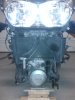
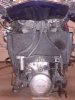
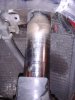
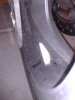
The forks come out just like the manual says. It does help to loosen the top pinch bolts and loosen the caps while still mounted on the bike. Mine weren't tight at all and came loose easily. I took a picture of how high the forks were mounted; it appeared they were just flush with the top bridge so that's where they went back on at too. Once the pinch bolts are removed, the forks slide right out. I had all the plastic off already but it's been said here that you can do this job without removing any. It will be more difficult to get to the bolts, but it can be done. To me it's not that hard to remove the plastic and it also gives me a chance to take a look around inside to check for wire chaffing, etc while it's off. You can see there is also a spot on the radiator where it looks like fluid has been blown onto it on the left side of the bike.
I don't have a stand so just put the bike up on the center stand and blocked up the front end to remove the wheel. Be aware that with the forks also gone, there isn't enough weight forward and the bike will settle onto the rear wheel. I don't recommend removing the supports though because you never know when work pressure will cause a shift back in the forward direction and it would be a bad thing to pivot onto the floor with the wheel and forks gone! Mine shifted back onto the wood blocks several times during the project.
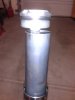
When you remove the caps, the upper part of the fork will easily slide down. There shouldn't be any fluid loss at this point as the forks are filled with the upper tubes at their lowest position. Below the cap is the spacer and spring; some tension may be required to get wrench clearance onto the nut at the top of the damper.
I took pictures and measured the fluid that was removed from both sides for comparison but they were relatively equal at about 400ml. Don't know what the level measurement was upon disassembly; didn't remember, or really care, to measure it at that point but I did expect the left would have less fluid than the right, which wasn't the case.
The fork protectors pry off easily; they are indexed and with the shield facing forward in 'protection' mode, they can't be installed incorrectly.
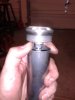
So off with the cap and then the spacer comes out. The spring is farther down, ie more difficult to reach, so the fluid got poured out at this point. Removing the bolt at the bottom of the fork (through the axle hole) wasn't as difficult as some have experienced. It felt like it was torqued properly and popped loose. Both oil locks slid right off the dampers for me, no issues there.
And they're removed by taking out a wire clip at the bottom of the damper. I found that pushing it in slightly to get it out of the grove, then just grabbing it and pulling it out was easiest. Just reverse the process on the rebuild. It snaps back into place nicely when you're ready.
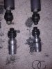
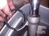
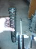
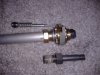
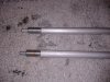
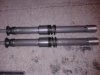
Here's what the bottoms of the forks look like with the clips, bottom valves, damper valves still installed on the damper rods and the damper tube to the left. The second picture shows the same things, just from a little more distant perspective. The top one is still 'assembled', the bottom is dissected a little further for relational viewing.
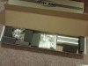
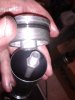
Enter the Race Tech kit!! The valves in my kit, and I assume any future kit, were already built up for the ST1300 and were labeled C and R and packaged as sets. There was little guessing as to which went where but just to prevent confusion, I did only open one package at a time during the rebuild to prevent getting things wrong. The bottom valves and damper valves go together into the same fork as a set so there is potential for screwing this one up. Race Tech recommends using the right fork for rebound and the left for compression so that's what I went with.
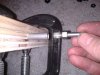
Some of the other articles talk about having to grind off the bottom nut to remove the valve stack. I did this on the first but it's not required with this kit because you just hold the rod and unscrew the valve assembly in its entirely. The dimple in the aluminum doesn't cause any distress, neither does the threadlock. Just don't crimp the tube while you're holding it. I jury rigged a clamped block with a hole drilled in it and also had to put a wrench on the other end (that is under the cap with the nut...) to hold it. I think the aluminum block is used for this but that didn't occur to me at the time so I made it work another way - improvise, adapt, overcome!
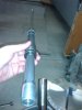
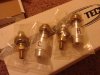
The right hand picture above shows the old damper valve (bottom), the new gold valve (installed with thread lock) and the needle that goes inside the tube down into the valve for the adjusting rod to work on. The o-rings for the needles were in my kit. However there were no o-rings for the bottom valves so I reused the ones from the stock valves. Louie said there should have been some in the kit but I took pictures of it right out of the box and there aren't any in the photos...so I didn't lose them in the 6 mos it took to get around to the install. Check for them or you'll have to find suitable replacements to finish the installation.
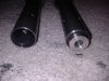
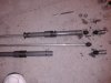
Here are both ends of the damper assemblies with the oil caps back on and the adjusting rods installed. Notice in the picture from farther away the 'new' holes in the compression damper. The instructions say to drill 4 1/4" holes at the top of the damper cartridge. This cartridge now becomes the compression cartridge and needs to go into the left (in my case) fork. Yet another reason why I did one completely at a time so the valves would end up in the right place.
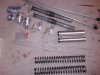
To take the upper tubes out of the lower forks, there is a snapring and seal, then the tube pulls out to reveal the bushings. There is a backup ring just under the oil seal, then a slider bushing and a fork tube bushing. Mine looked like they were ok so I didn't do any replacements here.
That's the end of the pictures (guess I had more than 30). The pictures are also in my album if you want to see the tube bushings and disassembly pics.
Reassembly was straightforward. The oil I used was Honda (red) SS-8 10wt, filled to 130mm. I put one washer under the spring and one on top before the spacer for preload, and because the instructions said to use one on either end of the spring; the spacers are already the correct length for the ST1300 when ordered, according to Race Tech. So far I'm still tweaking the preload and valves. The bike seems a bit 'jumpier' than I remember it being but hadn't ridden it for a couple months before I started the project. It also seems to 'hunt' a bit more than I remember but I suspect that's related more to the steering bearing change than the forks. All in all, a straightforward job. Now comes the hard part of getting it right for my 'ride' and enjoying knowing that I did it myself and can adjust things as required, should they need it. Don't be afraid to dig in on your own! This site, the service manual and the members are all here to help you and answer questions as you go. And in my opinion, the more you can wrench on your own ride, the better off you'll be for knowing how it ticks and how it should feel going down the road. While the forks were off I did my first (bike's second) valve check as well. Now it's back to working toward my first mileage award, hopefully before the end of the year.
Here's a comparison of the left and right forks (as viewed from the front), which is why I decided to go ahead and do this swap now. Started to see some fluid on the left fork and wasn't sure how much was still inside or what shape it was in. The wheel was getting coated as well. All indications that there was something amiss. No, I didn't use the 35mm film trick or the commercial product for helping to clear the seals. In my mind, if the fluid was getting that high up, it was time to put my well earned money (and well spent on the RC kit!) to good use.
The fender comes off fairly straightforward. The reflector clips have to be loosened for the bolt heads to clear, or removed entirely. I just loosened them. While it was off I put on my STuffSTopper...great product, went on perfect and so far has done the job...highly recommended if you're out of farkle ideas.
I removed the right side delay valve and crossover lines first; when it all went together, I think it would be easier in sequence to do the left brake hose clamp first but the manual says otherwise. Just be careful because there isn't very much clearance on the right side to get to the bolt heads with the hard lines there.
The forks come out just like the manual says. It does help to loosen the top pinch bolts and loosen the caps while still mounted on the bike. Mine weren't tight at all and came loose easily. I took a picture of how high the forks were mounted; it appeared they were just flush with the top bridge so that's where they went back on at too. Once the pinch bolts are removed, the forks slide right out. I had all the plastic off already but it's been said here that you can do this job without removing any. It will be more difficult to get to the bolts, but it can be done. To me it's not that hard to remove the plastic and it also gives me a chance to take a look around inside to check for wire chaffing, etc while it's off. You can see there is also a spot on the radiator where it looks like fluid has been blown onto it on the left side of the bike.
I don't have a stand so just put the bike up on the center stand and blocked up the front end to remove the wheel. Be aware that with the forks also gone, there isn't enough weight forward and the bike will settle onto the rear wheel. I don't recommend removing the supports though because you never know when work pressure will cause a shift back in the forward direction and it would be a bad thing to pivot onto the floor with the wheel and forks gone! Mine shifted back onto the wood blocks several times during the project.
When you remove the caps, the upper part of the fork will easily slide down. There shouldn't be any fluid loss at this point as the forks are filled with the upper tubes at their lowest position. Below the cap is the spacer and spring; some tension may be required to get wrench clearance onto the nut at the top of the damper.
I took pictures and measured the fluid that was removed from both sides for comparison but they were relatively equal at about 400ml. Don't know what the level measurement was upon disassembly; didn't remember, or really care, to measure it at that point but I did expect the left would have less fluid than the right, which wasn't the case.
The fork protectors pry off easily; they are indexed and with the shield facing forward in 'protection' mode, they can't be installed incorrectly.
So off with the cap and then the spacer comes out. The spring is farther down, ie more difficult to reach, so the fluid got poured out at this point. Removing the bolt at the bottom of the fork (through the axle hole) wasn't as difficult as some have experienced. It felt like it was torqued properly and popped loose. Both oil locks slid right off the dampers for me, no issues there.
And they're removed by taking out a wire clip at the bottom of the damper. I found that pushing it in slightly to get it out of the grove, then just grabbing it and pulling it out was easiest. Just reverse the process on the rebuild. It snaps back into place nicely when you're ready.
Here's what the bottoms of the forks look like with the clips, bottom valves, damper valves still installed on the damper rods and the damper tube to the left. The second picture shows the same things, just from a little more distant perspective. The top one is still 'assembled', the bottom is dissected a little further for relational viewing.
Enter the Race Tech kit!! The valves in my kit, and I assume any future kit, were already built up for the ST1300 and were labeled C and R and packaged as sets. There was little guessing as to which went where but just to prevent confusion, I did only open one package at a time during the rebuild to prevent getting things wrong. The bottom valves and damper valves go together into the same fork as a set so there is potential for screwing this one up. Race Tech recommends using the right fork for rebound and the left for compression so that's what I went with.
Some of the other articles talk about having to grind off the bottom nut to remove the valve stack. I did this on the first but it's not required with this kit because you just hold the rod and unscrew the valve assembly in its entirely. The dimple in the aluminum doesn't cause any distress, neither does the threadlock. Just don't crimp the tube while you're holding it. I jury rigged a clamped block with a hole drilled in it and also had to put a wrench on the other end (that is under the cap with the nut...) to hold it. I think the aluminum block is used for this but that didn't occur to me at the time so I made it work another way - improvise, adapt, overcome!
The right hand picture above shows the old damper valve (bottom), the new gold valve (installed with thread lock) and the needle that goes inside the tube down into the valve for the adjusting rod to work on. The o-rings for the needles were in my kit. However there were no o-rings for the bottom valves so I reused the ones from the stock valves. Louie said there should have been some in the kit but I took pictures of it right out of the box and there aren't any in the photos...so I didn't lose them in the 6 mos it took to get around to the install. Check for them or you'll have to find suitable replacements to finish the installation.
Here are both ends of the damper assemblies with the oil caps back on and the adjusting rods installed. Notice in the picture from farther away the 'new' holes in the compression damper. The instructions say to drill 4 1/4" holes at the top of the damper cartridge. This cartridge now becomes the compression cartridge and needs to go into the left (in my case) fork. Yet another reason why I did one completely at a time so the valves would end up in the right place.
To take the upper tubes out of the lower forks, there is a snapring and seal, then the tube pulls out to reveal the bushings. There is a backup ring just under the oil seal, then a slider bushing and a fork tube bushing. Mine looked like they were ok so I didn't do any replacements here.
That's the end of the pictures (guess I had more than 30). The pictures are also in my album if you want to see the tube bushings and disassembly pics.
Reassembly was straightforward. The oil I used was Honda (red) SS-8 10wt, filled to 130mm. I put one washer under the spring and one on top before the spacer for preload, and because the instructions said to use one on either end of the spring; the spacers are already the correct length for the ST1300 when ordered, according to Race Tech. So far I'm still tweaking the preload and valves. The bike seems a bit 'jumpier' than I remember it being but hadn't ridden it for a couple months before I started the project. It also seems to 'hunt' a bit more than I remember but I suspect that's related more to the steering bearing change than the forks. All in all, a straightforward job. Now comes the hard part of getting it right for my 'ride' and enjoying knowing that I did it myself and can adjust things as required, should they need it. Don't be afraid to dig in on your own! This site, the service manual and the members are all here to help you and answer questions as you go. And in my opinion, the more you can wrench on your own ride, the better off you'll be for knowing how it ticks and how it should feel going down the road. While the forks were off I did my first (bike's second) valve check as well. Now it's back to working toward my first mileage award, hopefully before the end of the year.
Last edited:
")
 Hey Gus1300... How about updates and opinions. Can you tell us what you felt, and how you adjusted to make it feel better.?:chat1:

 But you are right, the clamps on the steering head will hold the fork leg securely.