I'm working on a combination of projects and want to make a tweak to it but wondering if there's an easier way.
As I'm not really familiar with 2 of the components perhaps someone can chime in with their 2 cents.
Background:
Just installed dual horns, fed off a 4 pin relay.
I'd like to have the high beam circuit activate when the horns are activated.
Obviously I need to isolate the headlight high beam from the horns so the horns activate the high beam but the high beam doesn't activate the horns!
I can accomplish this isolation via a 5 pin relay but thought a diode would be a smaller and easier replacement.
Relays and bridge rectifiers I'm familiar with, a Schottky diode should be just a diode (yes with some special properties) and I've never used FET's before.
I likely have some of all kicking around in my goodie box of electrical components.
A 5 pin relay would work fine, a bridge rectifier is overkill, and I'm uncertain about the Schottky & FET suitability.
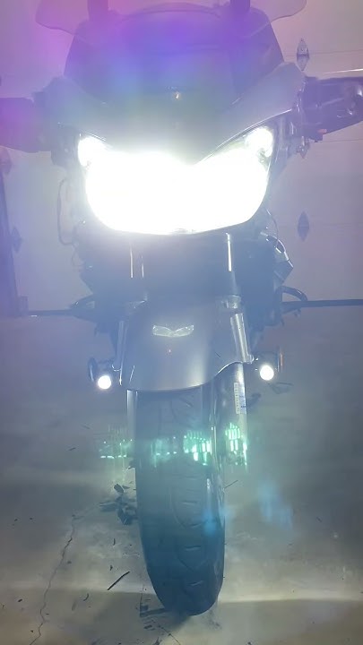
As a bit of an extra explanation of the diagrams, headlight bulbs have been replace with F2 leds. 72w each.
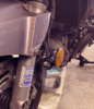
I've also bought switchback DRL's (the small zmoons) I'm going to fork mount.
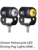
The plan for those is to use the amber LED emitters tied to my bike's low beam and the white LED emitter tied to the high beam.
I'll use a 5 pin relay for that with the amber LED on the normal closed loop and have the high beam trigger the relay to switch to the white LED instead.
Feed power to the 5 pin relay with have a master on/off switch and be fed from a switched power supply. They draw about 60w max for the pair. (30w per color per light)
I might also put a strobe unit in to make the high beam actually flash and the DRL's alternate from yellow to white while the horns are activated, but that's out of scope for this discussion and not in the diagrams.
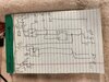
If I do a 5 pin relay for the high beam headlight flash I'm thinking this: Horn button activates the new horn relay sending power to the horns and the flasher relay which illuminates the high beams and switches the amber DRL to white as well. The relay is wired so the regular high beam circuit is always active from the headlight switch.
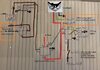
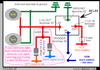
Edit: Above is an old diagram. See the "new" diagram further on below.
Still used 3 relays (1 horn, 1 headlight, 1 driving light.)
Added a bridge rectifier to prevent a feedback circuit and rerouted the headlight flasher power from the low beam circuit, not the high beam as per above.
That's it.
Please pick away at any flaws you see, or add any suggestions you care to make.
As I'm not really familiar with 2 of the components perhaps someone can chime in with their 2 cents.
Background:
Just installed dual horns, fed off a 4 pin relay.
I'd like to have the high beam circuit activate when the horns are activated.
Obviously I need to isolate the headlight high beam from the horns so the horns activate the high beam but the high beam doesn't activate the horns!
I can accomplish this isolation via a 5 pin relay but thought a diode would be a smaller and easier replacement.
Relays and bridge rectifiers I'm familiar with, a Schottky diode should be just a diode (yes with some special properties) and I've never used FET's before.
I likely have some of all kicking around in my goodie box of electrical components.
A 5 pin relay would work fine, a bridge rectifier is overkill, and I'm uncertain about the Schottky & FET suitability.
As a bit of an extra explanation of the diagrams, headlight bulbs have been replace with F2 leds. 72w each.
I've also bought switchback DRL's (the small zmoons) I'm going to fork mount.
The plan for those is to use the amber LED emitters tied to my bike's low beam and the white LED emitter tied to the high beam.
I'll use a 5 pin relay for that with the amber LED on the normal closed loop and have the high beam trigger the relay to switch to the white LED instead.
Feed power to the 5 pin relay with have a master on/off switch and be fed from a switched power supply. They draw about 60w max for the pair. (30w per color per light)
I might also put a strobe unit in to make the high beam actually flash and the DRL's alternate from yellow to white while the horns are activated, but that's out of scope for this discussion and not in the diagrams.
If I do a 5 pin relay for the high beam headlight flash I'm thinking this: Horn button activates the new horn relay sending power to the horns and the flasher relay which illuminates the high beams and switches the amber DRL to white as well. The relay is wired so the regular high beam circuit is always active from the headlight switch.
Edit: Above is an old diagram. See the "new" diagram further on below.
Still used 3 relays (1 horn, 1 headlight, 1 driving light.)
Added a bridge rectifier to prevent a feedback circuit and rerouted the headlight flasher power from the low beam circuit, not the high beam as per above.
That's it.
Please pick away at any flaws you see, or add any suggestions you care to make.
Last edited:

")