OP
OP
Thanks for the replyThat is a good find, Roger, and would certainly produce the symptoms that you have been showing us.
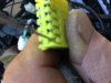
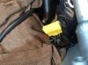
I have never seen that yellow 'connector' - so all of the black / white cables go into the connector, and the fitting of the cap connects them all together ?
Yes, it's just like the Yellow ground joint connector in the right front fairing where all the conductors are connected via a brass strip with legs. No one has seen it as it is taped up within the main harness along side a pink joint connector which houses another set of ground connectors. Looking at harnesses, it's just a big hump like a snake that ate a rat.
Not that it makes much difference electrically, but all the black/white cables come together at one point - not because they need to be connected together, but because they all need a power supply. Since the cap isn't on, all of the cables are disconnected from each other. You should be able to quickly work out which was is providing the 12v and whether it is one of the damaged cables or whether it is still intact in the yellow connector. The power, incidentally, comes from the output terminal of the Bank Angle Sensor Relay when the Bank Angle Sensor turns the relay on. The source of the 12v power is via the Black / Pink cable which comes from a 20A fuse in the rearward fuse box.
Correct
You could locate a second hand terminal block and then fit the wires into that. The terminals, by the way, can usually be released by pressing down a latch of metal on one side of the terminal itself. It usually requires a tool or a small watchmakers screwdriver. I can provide some photos of terminals that look to be similar if you are unsure about this.
ive done this with other style connectors, it takes some patience, and I can never remember witch end of the connector to approach it from
Alternatively, as previously suggested, you could install a new connector into which the damaged wires could be placed. They would need to be fed from the same power supply as the others - ie the output Bl/W cable from the Bank Angle Sensor Relay, and this would need to be have enough wires spliced from it in order to feed each of the newly located damaged wires.
If the 12v supply is one of the damaged wires, then I would fit a new terminal and put it into an undamaged slot in the old yellow connector. Take out one of the others for this, and put the ejected cable into your new connector instead.
Now - you don't know what current these cables are going to be carrying, but you do know that the total current doesn't exceed 20Amps. So the new power feeds have to use 20Amp cable. I find the newer thinwall stuff to be better to work with.
There is no need to connect the new connector to the existing yellow block - everything will be connected via the power supply from the output of the bank angle sensor relay. I am assuming that the yellow cap connects everything together here. I am also assuming that the existing 12v feed from the relay is good.
i believe the power supply from the BAS relay is one of the affected conductors, I will test to be sure. If I were to use the existing connector Parrelled with a new connector, I would have to piggy back the two in order to have power to both. There is only one remaining good slot in the existing connector so the BAS relay power B/W conductor would need to feed a new joint connector, along side the other affected conductor and a jumper from the new conductor to the remaining good slot in the old.
Finally, you may want to check what might have caused the problem in the first place. It could be corrosion, reducing the conductivity of the cable / terminals and increasing the heat. It could be that someone looking for a convenient 12v supply had been told to tap into any bl/w cable in the harness, and then ran something like an 18amp horn off it ! It might be that a problem of this nature has already been removed.
Thats what I was thinking and will investigate. As a former PD bike, someone could have powered something like the 200W siren off of it. (No siren at this point) Currently my major accessories, police lights, Clearwater lights and heated gear harness are powered off the battery. The Clearwater light trigger conductor, GPS and digital volt meter are on the quarterlet harness
As mentioned previously by someone. Use dilectric grease on all terminals to protect them. If splicing / joining wires - make sure that they are physically sound. Grease them too and protect them.
---------------
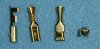
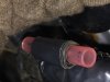
From the photos, those terminals in the yellow block look very much like the terminals used in the Hitachi 2P, 3P, 4P, 6P and 9P connectors. I can send you a quality photo with dimensions - if they are the same, then it should be easy enough to buy new ones.
[Edit]
Here you are - you may be able to tell if these are the correct ones for that yellow block.
16.5 mm long, 4.2mm wide, 2.65mm high (excluding the 'latch')