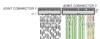
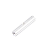
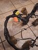
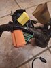
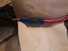
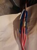
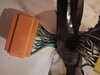
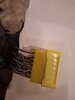
I have removed the protective cover from the wiring harness of an ST1300, model 2008 with ABS. This reveals a few things under the black protective cover.
holm from germany
It goes on.
holm from germany
It goes on.
Attachments
-
 150.6 KB Views: 64
 -
 93.6 KB Views: 63
 -
 56.9 KB Views: 64
 -
 64.8 KB Views: 64
 -
 66.9 KB Views: 63
 -
 57.2 KB Views: 62