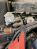
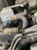
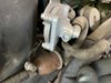
I bought an ST1100 year 97 that I am going to restore. It was very poorly maintained. I will be grateful if you indicate where the hose indicated in pictures 1 to 3 is connected and if the hoses shown in picture 4 are correct.

You are using an out of date browser. It may not display this or other websites correctly.
You should upgrade or use an alternative browser.
You should upgrade or use an alternative browser.
Hose Connection
- Thread starter Martin Schneuer
- Start date

Those hoses are not in those positions on my 1100, so without knowing where the other ends are connected to, it is hard to say where they need to go, or if they are superfluous to your needs.
Welcome to the forum and good luck with your project!
Here are a couple pics from my collection of other peoples pictures.
.jpg")
.jpg")
OP
OP
Hello and thank you for all your replies.
I bought the 1997 ST 1100 Paneuropean non ABS which is a Police version that was imported and used by an hospital. Not sure if it had all the police accessories. When the hospital sold all the fleet, some accessories were taken out. Being DeanR pictures I discovered that there are several versions with different design for what I am looking.
My english is also no good since I am a spanish speaker that live in Santiago, Chile, South America.
The bike was poorly maintained, has 63.000 miles, originally white

 and later was painted red and now is black. Mechanically everything works, the motor leaks oil from one or more parts, no blue smoke but smell as very poor combustion, suspension leaks also and brakes are nor efficient.
I am a retired engineer and bought the bike because the price was half of a commercial price and my intention is to restore it.I just started dissembling it and if I do not find a big surprise with something wrong, I will continue working in it trying a good restoration and painting it red.
Thanks in advance for your help.
I bought the 1997 ST 1100 Paneuropean non ABS which is a Police version that was imported and used by an hospital. Not sure if it had all the police accessories. When the hospital sold all the fleet, some accessories were taken out. Being DeanR pictures I discovered that there are several versions with different design for what I am looking.
My english is also no good since I am a spanish speaker that live in Santiago, Chile, South America.
The bike was poorly maintained, has 63.000 miles, originally white
and later was painted red and now is black. Mechanically everything works, the motor leaks oil from one or more parts, no blue smoke but smell as very poor combustion, suspension leaks also and brakes are nor efficient. I am a retired engineer and bought the bike because the price was half of a commercial price and my intention is to restore it.I just started dissembling it and if I do not find a big surprise with something wrong, I will continue working in it trying a good restoration and painting it red.
Thanks in advance for your help.
CYYJ
Michael
I will be grateful if you indicate where the hose indicated in pictures 1 to 3 is connected and if the hoses shown in picture 4 are correct.
Hi Martin:
Welcome to our forum.
If you go and read this article: ST1100 - How to do an emergency bypass of the fuel valve, it will explain to you exactly what the previous owner did that resulted in the hoses looking the way they do now.
If you wish to restore the bike to exactly original condition, you will need to buy a new fuel shutoff valve and then re-connect the hoses in their original positions (shown in the above-referenced link). But, this is not "urgent" - the bike will run fine with the fuel valve bypassed, and it looks like you have other, more important things to spend your money on before you replace that fuel valve and return the hose plumbing to normal.
Michael
Michael,
It appears the fuel cut off valve IS connected and there is a third, unknown hose there.
OP
OP
Thank you Micael and Bush.
I looked my bike and agree with the observation from Bush (fuel cut off wave is connected and unknown hose not connected)
I looked my bike and agree with the observation from Bush (fuel cut off wave is connected and unknown hose not connected)
John OoSTerhuis
Life Is Good!
You are communicating just fine, Martin. Welcome!
My guess is that the unplugged hose in your first three pictures is the crankcase breather hose that connects to the bottom of the air cleaner housing.
The hoses in the fourth picture appear to be a bad repair of the #2 and #4 cylinders’ intake manifold vacuum port hoses (left front and rear cylinders). The front hose in your picture looks like the #2 vacuum port. It is plugged into a “T” connector like that used on USA models’. This T on ours links the #2 and #4 vacuum ports, with the third hose leading to and providing vacuum to the PAIR system valves under the carbs. The center leg on your T has a short length of hose that is plugged on the end. The other leg has non-Honda, clear PVC hose hose leading back under the carbs. I’m going to assume it is connected to the #4 cylinder intake manifold vacuum port. Please confirm. If not, what were they tapping vacuum from the engine for? And where is the #4’s vacuum hose?
If your ST was produced and manufactured for a market not requiring the PAIR system, I’m not sure what the fourth picture is showing. My guess is that you can just install your own new, quality vacuum hoses to each port and cap them with removable plugs. Make the hoses long enough to make it easy to do a carburetor synchronization.
A Honda Service Manual would be a great help to you I’m sure. Good luck with a worthy project!
John
Last edited:
OP
OP
Thank you John for your detailed explanation. Seems you know the bike a lot.You are communicating just fine, Martin. Welcome!
My guess is that the unplugged hose in your first three pictures is the crankcase breather hose that connects to the bottom of the air cleaner housing.
The hoses in the fourth picture appear to be a bad repair of the #2 and #4 cylinders’ intake manifold vacuum port hoses (left front and rear cylinders). The front hose in your picture looks like the #2 vacuum port. It is plugged into a “T” connector like that used on USA models’. This T on ours links the #2 and #4 vacuum ports, with the third hose leading to and providing vacuum to the PAIR system valves under the carbs. The center leg on your T has a short length of hose that is plugged on the end. The other leg has non-Honda, clear PVC hose hose leading back under the carbs. I’m going to assume it is connected to the #4 cylinder intake manifold vacuum port. Please confirm. If not, what were they tapping vacuum from the engine for? And where is the #4’s vacuum hose?
If your ST was produced and manufactured for a market not requiring the PAIR system, I’m not sure what the fourth picture is showing. My guess is that you can just install your own new, quality vacuum hoses to each port and cap them with removable plugs. Make the hoses long enough to make it easy to do a carburetor synchronization.
A Honda Service Manual would be a great help to you I’m sure. Good luck with a worthy project!
John
I will continue disassembling the bike. It will take some time to disassemble the carbs and find if it is the cranks breather and the intake vacuum hoses bad repair. For sure the previous owner o their mechanics did a terrible work.
I will take pictures and inform my findings to you and all gentlemen who has collaborated in this topic.
No doubt I will find more doubts in my restoration progress and ask this forum.
So far I got the user and shop manual.
I need to find where to buy the fairing fasteners and whichever spare part I will need,... at reasonable prices.
Saludos (cheers).
Martin.
Hope you get it sorted out and welcome to the forum!Thank you John for your detailed explanation. Seems you know the bike a lot.
I will continue disassembling the bike. It will take some time to disassemble the carbs and find if it is the cranks breather and the intake vacuum hoses bad repair. For sure the previous owner o their mechanics did a terrible work.
I will take pictures and inform my findings to you and all gentlemen who has collaborated in this topic.
No doubt I will find more doubts in my restoration progress and ask this forum.
So far I got the user and shop manual.
I need to find where to buy the fairing fasteners and whichever spare part I will need,... at reasonable prices.
Saludos (cheers).
Martin.
OP
OP
Thank you Bikeric
John OoSTerhuis
Life Is Good!
If you go and read this article: ST1100 - How to do an emergency bypass of the fuel valve, it will explain to you exactly what the previous owner did that resulted in the hoses looking the way they do now.
If you wish to restore the bike to exactly original condition, you will need to buy a new fuel shutoff valve and then re-connect the hoses in their original positions
Take another look at Martin’s pictures, Michael... the Auto Fuel Valve (vacuum “petcock”) is in fact correctly installed. The bypass mod has not been done to this ST. There is no need to apply the bypass right now.
I hope this didn’t confuse Martin too much.
Edit: I just reread the thread and see my friend Forest noted the same thing.
John
I agree with John, the loose hose is the crank breather that connects to a stub on the underside of the airbox. If you remove the air filter lid and filter, you can access the 6 screws that hold the airbox lower to the top of the plenum, with those off you can lift the airbox lower (need to flex the intake trumpets a bit here) and you'll be able to see the nipple that the hose connects to. I'd suggest you keep digging and get the carbs out for a clean, maybe replace the bowl gaskets and the intake rubbers (new ones make for a good seal and make reinstallation much, much easier).
I'll be taking some pictures and posting them later tonight. You are lucky, My ST1100 is getting torn down for a carb re-build and I'm waiting for parts. I have just what you need!
It soundls like you have the right side figured out and that leads to the nipple on the bottom of the air filter. But that left side....
I think it is tubing fromt he Emiisions Control System and the vaccum activates one of the PAIR valves (Pulse Secondary Air Injection). This looks like it is the rear valve.
It looks like they pulled the front line off the nipple under cylinder number 2 (front left) and plugged it. They are only using the vaccum from cylinder number 4 (left rear).
In the normal configuration the "T" is centered between the carberatures and the tube that leads over to the PAIR valve is routed between the carburators. Whoever did this... it looks like they ran a new hose around the back of the motor and I would bet it is plugged into the PAIR valve "T" under the carbs toward the right rear.
I would bet the line was no good at some point and this was a creative way to try to fix it.
Pics coming. But, if you have a service manual, you can take a look at 1-43 (that's chapter 1, page 43) and I believe the part you are locking at is on the bottom diagram labeled "(16) - No, 10 tube"
John OoSTerhuis
Life Is Good!
I see you agree with my post above, Dale. The one OEM hose shown may be the #4 cylinder’s intake manifold vacuum port hose; which begs the question, “where is the #2 cylinder’s hose?”
Martin, here’s a picture in one of my albums that shows the vacuum hoses arrangement under the carbs of my PAIR equipped ST1100:
http://www.st-riders.net/coppermine/displayimage.php?album=40&pid=962#top_display_media
The vacuum “T” connecting the three hoses is just out of view under the left framemember.
Here’s the link to the whole album:
Carb Hoses R&R...
I hope this helps.
Regards, John
Last edited:
John OoSTerhuis
Life Is Good!
Finally found a picture in my archives of the hoses. The #2 and #4 vacuum port hoses have been separated from the “T” and plugged into the short metal tubes on the ends of the clear PVC manometer hoses; set up for a carb sync. The T is still attached to the PAIR (air suction valves) system. FWIW

John
John
Last edited:
OP
OP
Thank you John, Terry and Dale for your help.
Wow, I really appreciate the time and information you are providing. Excellent and again, thanks a lot.
I need to study your information and Service Manual. Today I took out all the fairings out. The ST100 was painted twice by previous owners and their mechanics lost many bolts that were not installed, about 60% were replaced by fasteners without a collar creating damage in the plastic. As soon as I have time I will resume the work and get my hands in the carbs. I will inform you my findings.
The following pictures gives you some idea where I am now.
Late night for me. Looks like John's got it. Where the hoses leave the left cylinders and dissappear off John's view.... here is what it look like just outside of his picture:

The two vaccum ports join together and the "T" going between the carbs in my shot ends up in a T just forward of the rear PAIR valve. John's picture above really shows it well. This shot is taken from the back of the engine looking forward (my gas tank is currently removed).

Here is the diagram from the manual I referenced earlier. Looks just like John's photo!

The two vaccum ports join together and the "T" going between the carbs in my shot ends up in a T just forward of the rear PAIR valve. John's picture above really shows it well. This shot is taken from the back of the engine looking forward (my gas tank is currently removed).
Here is the diagram from the manual I referenced earlier. Looks just like John's photo!
I should mention... there is a good reason to have those lines come up where they are easily accessed. In John's picture above someone is syncing their carbs and these lines are tapped to measure vacuum during that procedure.
Share: