ST1100 SMC for ABS/CBS models
I thought that I knew how to put this thing back together again, having done it a couple of times before. But when I tried last year having not touched an 1100 since 2006 - I needed the diagram to refer to. That didn't help a great deal either - with arrows going all over the place. I eventually got it sorted, but thought that there had to be an easier way.
I don't know whether these diagrams help, but I did most of them at the time and thought that they ought to be on here. Anyway I enjoyed the colouring in !
1. The main components.
 Here we have the main components of the SMC assembly.
Light blue - the master cylinder itself
Pink is the 'Arm Set'. I tend to refer to it as the Ace of Clubs Linkage. This has a bushed hole (light blue) and two needle roller bearings with oil seals.
The bush inside the roller bearings protrudes at each end so that when everything is bolted together, the arm is free to move.
The bushed hole in the linkage (shaded light blue on the pink Ace of Clubs Link) is connected to the bracket on the bottom end of the Master Cylinder.
In grey are the two plates - called Plate A and Plate B on the Honda fiches - the one at the back (top in the image) has threaded nuts welded to the back of each hole.
2. The SMC link to the Ace of Clubs Linkage.
 There is a clevis pin and a split pin. The bracket on the end of the Secondary Master Cylinder (SMC) is secured to the Ace of Clubs link with the clevis pin, and the clevis pin is secured with a split pin through a hole in clevis pin after is is pushed into place.
The head has a thin, flat head. It is circular, has a section that is ground flat. This corresponds to the flange that is kbent over at the bottom of the SMC bracket - visible in the diagram. This stops mthe pin from turning and therefore preventing the split pin at the opposite end from being worn away.
This assembly needs to be quite thin so that the bracket needs to be able to move freely in between the two plates.
The clevis pin needs to be greased - not to aid movement, but to protect it from corrosion. Brake pad grease such as Ceratec, or a smear of Moly 60 - both seem to have the ability to stay put in harsh conditions.
3. The assembled components.

Missing from the previous diagrams are two essential components : The fork leg and the caliper bracket.
Both fixing points on the left fork leg have a bush inside a needle roller bearing and this needs to be greased. There are also oil seals.
The left hand side of the curved plates are bolted to each side of this bush. The front plate, the bush and the rear plate are bolted firmly together onto the fork leg. The plates are fitted so that there is a gap between them for the SMC bracket and clevis pin to move without touching,.
They should pivot easily in the bearing although final tightening should be left until later.
The clevis pin is already secured in the bushed hole of the Ace of Clubs link, but I have not shown this in the diagram on the left. it makes it easier to recognise the SMC bracket behind the visible plate.
The other two holes in the Ace of Clubs link both have bearings with a protruding bush. The centre bush in the Ace of Clubs link is clamped between the right hand side of each of the plates.
The bottom end of the (light blue) master cylinder sits between the two Igrey) curved plates. The master cylinder bracket should not touch the plates..
The remaining bearing in the ace of clubs link is fitted between the two arms of the brake caliper bracket. In fact the bolts only function is to clamp the bush to the inner arm of the caliper bracket. The hole in the outer arm of the caliper leaves a tiny gap around the bolt head. A little grease around that outer hole will help prevent corrosion.
4. The Workshop Diagram
Below is the colour coded diagram that is in the workshop manual. I haven't rearranged anything in this. I've used the same colours as before to try to highlight the components. The the arrows in the o.riginal - to show where each part of the diagram is connected to another part - are also colour coded.
I have removed the arrows and the torque settings for each bolt from the original Honda diagram - which helps to simplify it somewhat.
The operation of the linkage is quite simple. The caliper bracket is moved up when the brakes are applied due to the rotation of the disk, so the SMC bracket is also pushed up. The odd linkage allows the caliper bracket to move in an arc but the master cylinder push rod is moved straight up.
If any of this mechanism seizes up, then the SMC cannot be activated as it should. But there is plenty of force when braking to make sure that it does. Applying the brakes is not a problem. But allowing them to release afterwards is. If your rear brake is always too hot to touch after a ride then this linkage may be the problem.
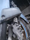
The mechanism is largely hidden behind that grey shroud, and it can go years without attracting the attention. Yet done regularly, it is a straight forward job - although removing the grey shroud may be an issue - it is screwed from the inside of the mudguard.
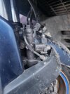
 5 A Photo of the item itself

An image that I found on the web of the linkage as a part for sale.
The unattached end of the plate will be rotated anticlockwise and bolted through the fork leg bearing.
The clevis pin will be between the two plates - and the SMC bracket will be attached to that.
The free bearing in the Ace of Clubs link will be attached to the caliper bracket.


 . As I said the braking feels solid, but not sure if this is a known issue with aged bikes.
 that would be great. “