My personal view on facing wiring issues.

Joined
Oct 4, 2024
Messages
106
Location
Spain
Bike
ST1300
Hello everyone. I vowed to post a thread about fixing wiring and electrical issues.

There's a difference between "electronics" and "electrical" stuff. The first one involves semi-conductors and the second one just wires, switches, interruptors, some voltage variators, just a few stuff. But specially connectors and wires.

The thing is that electronics usually is not very worky but really complex and in the other paw electrical stuff can be really worky but not that complicated. That's why if you have a pair of good hands and some eyes with some sight in them you can fix electrical issues too. It requires almost the same amount of neurons than breathing, breeding and eating.

So, I'm posting to you how I get to lose the fear to wires and their issues. This wil be a lot of posts about the thing, I'm a bit low of minutes to spare so I'll be doing from time to time, specially for adding answers to questions you could have.

The first thing, and the very first one you should base your wiring action on, is that knowing electrical stuff will not help you at all if you don't fusion that knowledge with the WORKSHOP MANUAL of your vehicle. The wiring scheme, the correct one, for your vehicle, any vehicle, is MANDATORY to study it in order to achieve finding and solving issues.

After having that scheme, it's all about reading colors and following wires and working a damned lot spreading wires like hay when looking for that needle. The thing is that the scheme is a freaking big magnet and help the biggest lot and that's its purpose, to reach that needle. It's very frustrating and it will let you down, but after finding two or three electrical issues, you'll find that it was not that big of a matter. It's just about time and work looking into it, following some very basic electrical logic and the wiring scheme.

That very basic electrical logic is as simple as this: One wire takes energy from one point to the other, and should not lose it on its way. An interruptor cut that way. A switch changes from one way to some other. And all of that path should be clean and isolated.

That's it. You now know all the electrical theory you need to fix electrical issues. From that, all the other stuff you need will come as common sense (Do you have of that? Surely you do!)

Now, this thread is about the technical abilities to apply that knowledge and wiring schemes:

- How to find issues.
- Tools needed.
- How to make new wires.
- How to change and fix connectors, interruptors, switches, etc.
- How to choose the proper wires (they are very different!).
- How to work with fuses.
- How to substitute damaged wires or find wheretheheck that wire should go.
- How to make proper connections between wires, using tin and shrinkable tubes and other tools.
- How to use a multimeter on it (I'm not telling the very basic thing about it, that's a very talked issue. I'm going into a bit more advanced uses).

Well, this is an introduction on the thing. Please let me know what you want to know so I make a good planning for the coming posts.

Best V'ss and regards.
 
This can be a very interesting thread. I look forward to reading your thoughts and hopefully learning a few tricks. Electrical trouble shooting can sometimes be frustrating. Having a bit more knowledge and a few extra tricks up ones sleeve is never a bad thing.

- How to use a multimeter on it ......
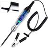
While I believe that a multi-meter is a necessary and important part of any tool kit that will be used for diagnosing and troubleshooting electrical circuits, with regards to 12V DC electrical systems like are found on motorcycles it is my opinion that it is over used in place of the tool that should often be the first choice- the 12V test light. For most, not all, 12V DC electrical (not electronic) trouble shooting the test light is far simpler to use, much faster to use, and because it introduces a load in to the circuit being tested it will often provide much more reliable and valuable test results.
 
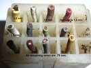
Ha, I'm just in the process of doing a 33 year revamp of the wiring from my Flexit sidecar to the bike. Because the Flexit and bike lean the connections between the bike and sidecar are not static and this can lead to a few issues, most of which have been sorted with temporary fixes. Also, because the original concept of the Flexit was that it could be removed and put back on the bike as required, the electrics, and hydraulics to the sidecar brake, came with connectors to allow easy removal/installation. The original electrical connector is very basic with a 15 pin plastic connector of which 12 are used, but just to make life a bit more interesting the wires consist of one 2.5mm, two 1.5mm and nine .75mm. Photo gratefully provided by a US Flexit owner!

Wire gauges at connector.jpg

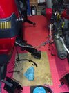
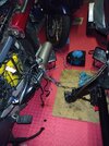
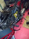
And just to make you all scream with horror, now that I have removed all the PVC tubing that used to enmesh the wires and hydraulic brake coupling, this is what I am left with (including what is behind the seat in the sidecar) :oops:

DSC_0006.JPGDSC_0007.JPGDSC_0008.JPGDSC_0009.JPG

It did look a 'little' tidier before I removed the covering tubing but there is a fair amount of work to do. The single connector is going to be replaced by two. One 2 pin for the 2.5mm and probably an additional earth and then a 12 pin for the 1.5mm and .75mm wires. To make my life easier I have purchased pre-wired deutsch connectors, one two pin 12AWG and one twelve pin 16AWG. These will be spliced in the sidecar loom using self soldering shrink connectors (something I have never done before so I will be practicing before I actually attack the work proper). The internal sidecar wiring will also be tidied and 'temporary fixes' (now about 25 years old) replaced with the correctly coloured wires. On the bike side, the wires linking lighting, brake lights and indicators (all connected by Watsonian 33 years ago) are going to be replaced and my intention is to use a trailer relay to feed the sidecar rather than just feeding directly from 'scotchlock'd' wires into the relevant circuits.

And just to make my life more complicated the wiring diagram that came with my owners guide (again, 33 years ago) bears absolutely no relation to my wiring colour wise. Thankfully, I found one on the internet from the US that seems to be just about right although I have a superfluous white wire that I will have to track down in the nose of the sidecar to see if it is attached to anything - I suspect it was the feed for a main beam had a hi/low light been fitted!),

Wiring Diagram 1991-1994.jpg

Wish me luck :D
 
Last edited:
... I'm just in the process of doing a 33 year revamp of the wiring...
See my above remark about covering the basics first...

- mechanical skills; know your tools, how to remove a panel and disconnect/unpin a multi connector shell without braking it...
- understanding electricity; AC, DC, voltage, resistance, current, ID-ing components, deciphering an existing wiring vs a diagram...
- automotive knowledge; how to place, route & secure wiring, what gauge and sleeving, what type of connectors, how to crimp (anything)...

I've seen things, awful things...
 
I'd start there...

0_4zDYVpNIQFptSLJh.png

Yup, that's a basic one. I'm talking about that when chosing wires and connectors. Sometimes people get wires like damn sticks when something like a hair is enough. Same with connectors. Some uses really don't need big connectors, which are also more expensive than the correct ones.
 
This can be a very interesting thread. I look forward to reading your thoughts and hopefully learning a few tricks. Electrical trouble shooting can sometimes be frustrating. Having a bit more knowledge and a few extra tricks up ones sleeve is never a bad thing.


While I believe that a multi-meter is a necessary and important part of any tool kit that will be used for diagnosing and troubleshooting electrical circuits, with regards to 12V DC electrical systems like are found on motorcycles it is my opinion that it is over used in place of the tool that should often be the first choice- the 12V test light. For most, not all, 12V DC electrical (not electronic) trouble shooting the test light is far simpler to use, much faster to use, and because it introduces a load in to the circuit being tested it will often provide much more reliable and valuable test results.

I understand your POV, but I'm going a bit further as a multimeter si easy to use and cheap, and I want to involve people into the thing of understanding amps, volts, and ohms. I pretend to get them to understand that if you have a 12,8 V in the battery, something's wrong if you ar getting 11,2 V where you are checking stuff. The lamp can be a bit misleading, specifically if someone gets a LED for it. If you have a good volt measure you can be sure about stuff that you cannot get without that reading. That's why I'm going there straight away.
 
Ha, I'm just in the process of doing a 33 year revamp of the wiring from my Flexit sidecar to the bike. Because the Flexit and bike lean the connections between the bike and sidecar are not static and this can lead to a few issues, most of which have been sorted with temporary fixes. Also, because the original concept of the Flexit was that it could be removed and put back on the bike as required, the electrics, and hydraulics to the sidecar brake, came with connectors to allow easy removal/installation. The original electrical connector is very basic with a 15 pin plastic connector of which 12 are used, but just to make life a bit more interesting the wires consist of one 2.5mm, two 1.5mm and nine .75mm. Photo gratefully provided by a US Flexit owner!

Wire gauges at connector.jpg

And just to make you all scream with horror, now that I have removed all the PVC tubing that used to enmesh the wires and hydraulic brake coupling, this is what I am left with (including what is behind the seat in the sidecar) :oops:

DSC_0006.JPGDSC_0007.JPGDSC_0008.JPGDSC_0009.JPG

It did look a 'little' tidier before I removed the covering tubing but there is a fair amount of work to do. The single connector is going to be replaced by two. One 2 pin for the 2.5mm and probably an additional earth and then a 12 pin for the 1.5mm and .75mm wires. To make my life easier I have purchased pre-wired deutsch connectors, one two pin 12AWG and one twelve pin 16AWG. These will be spliced in the sidecar loom using self soldering shrink connectors (something I have never done before so I will be practicing before I actually attack the work proper). The internal sidecar wiring will also be tidied and 'temporary fixes' (now about 25 years old) replaced with the correctly coloured wires. On the bike side, the wires linking lighting, brake lights and indicators (all connected by Watsonian 33 years ago) are going to be replaced and my intention is to use a trailer relay to feed the sidecar rather than just feeding directly from 'scotchlock'd' wires into the relevant circuits.

And just to make my life more complicated the wiring diagram that came with my owners guide (again, 33 years ago) bears absolutely no relation to my wiring colour wise. Thankfully, I found one on the internet from the US that seems to be just about right although I have a superfluous white wire that I will have to track down in the nose of the sidecar to see if it is attached to anything - I suspect it was the feed for a main beam had a hi/low light been fitted!),

Wiring Diagram 1991-1994.jpg

Wish me luck :D

Nice job! Looks a lot of work, but as I said before there's no big stuff, beside the work. Just following wires and get things tidy one by one, just hours of good work and all will get really nice!

I never heard before about "self soldering shrink connectors", can you post some pictures?

Thank for sharing.
 
Test lights are useful but can also be misleading. For example 8v will light up a test light but the system your testing requires 12v, does the light lead you to assume voltage is good? You can get a test light with a integrated voltmeter fairly cheap. But be aware of voltage range.


1793897102443.png
 
I understand your POV, but I'm going a bit further as a multimeter si easy to use and cheap, and I want to involve people into the thing of understanding amps, volts, and ohms. I pretend to get them to understand that if you have a 12,8 V in the battery, something's wrong if you ar getting 11,2 V where you are checking stuff. The lamp can be a bit misleading, specifically if someone gets a LED for it. If you have a good volt measure you can be sure about stuff that you cannot get without that reading. That's why I'm going there straight away.
A multi-meter can deliver very misleading results as well. A multi-meter can show that battery voltage is present if only a few strands of a wire are still holding on so it is telling you that that circuit can transmit voltage but it doesn't tell you that it can not carry enough current to do what it is supposed to do. I have been bitten by that misleading test result using a multi-meter. Testing the same circuit with a test light might well tell you that that circuit can't carry much current because the light will burn dimly* if there is less than battery voltage present at the test sight.
The above reference to battery voltage means a fully charged battery delivering over 12V.

*
This depends on the type of test light being used. An old style incandescent test light gives a good indication of whether or not there is excessive resistance in the circuit being tested because it adds a small load to the circuit.
 
Test lights are useful but can also be misleading. For example 8v will light up a test light but the system your testing requires 12v, does the light lead you to assume voltage is good? You can get a test light with a integrated voltmeter fairly cheap. But be aware of voltage range.
I never wrote that the test light is a replacement for, and renders obsolete, a multi-meter. In fact I wrote that a multi-meter is a necessary and important part of any tool kit.
In the above scenario the test light will not burn as brightly* at 8V as it would if there was over 12V present. This tells the tester that there is something wrong and that further investigation is needed.

Like all things the devil is in the details. Both testers are useful depending on what is being tested. If someone is performing simple checks such as for the presence of voltage and ground, or continuity testing, a test light is a much simpler and faster method of doing so. If there is deeper diagnosing needed, such as measuring for voltage drop, current leakage, etc., than a multi-meter might be better suited for the job.

*
What you describe is exactly why I have a test light with an incandescent bulb, it will burn less brightly if there is less than battery voltage present and this is usually quite easy to see. LED test lights do not do this, at least not the ones that I have used. The LED test lights that I have used have two problems. One is that they will illuminate as long as there is 8V or above. The second is that they do not introduce a significant enough load in to the circuit to be of any value like an incandescent bulb. As long as the minimum voltage threshold for that particular LED is present the LED always displays at the same intensity. There is no indication of a problem because they either on or off. The intensity of an incandescent bulb will vary with the conditions which is useful information for the tester if they know enough to interpret what they are seeing.
The above reference to battery voltage means a fully charged battery delivering over 12V.

LED test lights are more useful for diagnosing electronic circuits, as opposed to electrical circuits, where an incandescent test light can actually be harmful to the circuit.
 

I never wrote that the test light is a replacement for, and renders obsolete, a multi-meter. In fact I wrote that a multi-meter is a necessary and important part of any tool kit.
In the above scenario the test light will not burn as brightly* at 8V as it would if there was over 12V present. This tells the tester that there is something wrong and that further investigation is needed.

Like all things the devil is in the details. Both testers are useful depending on what is being tested. If someone is performing simple checks such as for the presence of voltage and ground, or continuity testing, a test light is a much simpler and faster method of doing so. If there is deeper diagnosing needed, such as measuring for voltage drop, current leakage, etc., than a multi-meter might be better suited for the job.

*
What you describe is exactly why I have a test light with an incandescent bulb, it will burn less brightly if there is less than battery voltage present and this is usually quite easy to see. LED test lights do not do this, at least not the ones that I have used. The LED test lights that I have used have two problems. One is that they will illuminate as long as there is 8V or above. The second is that they do not introduce a significant enough load in to the circuit to be of any value like an incandescent bulb. As long as the minimum voltage threshold for that particular LED is present the LED always displays at the same intensity. There is no indication of a problem because they either on or off. The intensity of an incandescent bulb will vary with the conditions which is useful information for the tester if they know enough to interpret what they are seeing.
The above reference to battery voltage means a fully charged battery delivering over 12V.

LED test lights are more useful for diagnosing electronic circuits, as opposed to electrical circuits, where an incandescent test light can actually be harmful to the circuit.
never quoted you. That test light is much more useful and faster than simple test light.
 
... I wrote that a multi-meter is a necessary and important part of any tool kit...
And in the trades we have a proverb:

"... wer mißt, mißt Mist..." (... he who measures, measures 💩...)

You'd need tome technical background/understanding about what those readings actually mean/indicate and how to interpret...
 
What would help me is a colour chart of wire that’s universal practice. For example we tend to associate a red wire as positive, black negative and orange going to a turn signal. Is there such a thing? Or is it each manufacturer sets out what each coloured wire’s designation for their own brand?

EDIT
I did find this.

General Common Conventions (Japanese & Modern Harnesses)

• Ground (-): Solid Green or Black with a Yellow stripe (varies by brand)
• Battery / Main Power (+12V): Red, Brown, or Brown with a White stripe
• Headlight High Beam: Yellow or Blue with a stripe
• Headlight Low Beam: White or Green
• Tail Light / Running Light: Brown, Blue, or Gray
• Brake Light: Green with a Red/Yellow stripe, Blue, or Red
• Left Turn Signal: Orange or Dark Brown (or Violet on some brands like Harley-Davidson)
• Right Turn Signal: Light Blue, Dark Green, or Gray
• Horn: Light Green or Black
 
Last edited:
A multi-meter can show that battery voltage is present if only a few strands of a wire are still holding on so it is telling you that that circuit can transmit voltage but it doesn't tell you that it can not carry enough current to do what it is supposed to do.
if you measure the voltage under the actual load condition, you would see that the voltage had dropped significantly across those few strands of wire and is the reason that not enough current is able to flow.

Perhaps its not practical to measure that voltage under load because you had to put a connector back together to apply the load, but other options are available like finding another voltage test point downstream, or as a last resort, piercing the wire insulation with a steel sewing needle and using that as a probe point.

I'm not disagreeing with your premise, just mentioning there are other alternatives available. And, since the test light has limited current draw capability, it still won't find all resistance-related failure points.
 
if you measure the voltage under the actual load condition, you would see that the voltage had dropped significantly across those few strands of wire and is the reason that not enough current is able to flow.

Perhaps its not practical to measure that voltage under load because you had to put a connector back together to apply the load, but other options are available like finding another voltage test point downstream, or as a last resort, piercing the wire insulation with a steel sewing needle and using that as a probe point.

I'm not disagreeing with your premise, just mentioning there are other alternatives available. And, since the test light has limited current draw capability, it still won't find all resistance-related failure points.
Everything that you wrote makes perfect sense and I don't disagree with any of it. Again, I am not claiming that the test-light is all that is ever needed for electrical diagnosing and that multi-meters are never needed. They are two different tools and both are useful for different purposes. One does some things better than the other and vice-versa. In many instances where people reach for a multi-meter they should be reaching for a test-light in my opinion. This is especially true in instances where people do not have the capacity to properly interpret what the readings that they are seeing on a multi-meter mean. On simple 12V circuits they might be better served with a simpler test-light.

If one of the lights on my vehicle is no longer functioning I need to know if it is simply a burnt out bulb, a blown fuse, or a problem with the circuit? The first thing I want to check is if there is both power and ground at the bulb connector. In this case these simple tests are done faster and easier with an incandescent test-light than a multi-meter. The test-light will also quickly tell me if there is a problem in the circuit leading to that connector because it will not burn brightly if there a significant voltage drop. This is simpler and faster than performing resistance and voltage drop tests on that circuit using a multi-meter. If further investigation is needed a multi-meter might well be required but these initial tests are better done with an incandescent test-light in my opinion.

On the other hand, if I am diagnosing an electronic circuit and I need to know if the resistance and voltage drop between various points in a sensitive electronic circuit are within specification I don't reach for my test-light, I reach for my multi-meter.

The choice of which to use all depends on what is being tested and what it is being tested for.
 
And in the trades we have a proverb:

"... wer mißt, mißt Mist..." (... he who measures, measures 💩...)

You'd need tome technical background/understanding about what those readings actually mean/indicate and how to interpret...
Another good point. If someone does not really understand what a multi-meter is telling them they can be led astray and led down a wrong path. Performing basic tests on simple primary circuits there is less of a chance of this with a test-light as it requires less knowledge to use.
 
My way of dealing with electrical issues:oops: is to have my riding companion (who is with me for most trips) along. He is electrical engineer and is very good a diagnosing/fixing issues if any crop up and moreover, seems to relish the challenge. Me?.....I hand him stuff and generally stay out of the road.:)
 
Back
Top Bottom