Another intermittent speedometer

Joined
Oct 4, 2007
Messages
83
Location
Tampa, FL
Bike
ST1300
2003 ST1300A with ~42k miles on it.

A few weeks ago I noticed the speedometer needle dropped to 0 mph while I was riding. It stayed at 0 for a few minutes until coming back up to the correct speed. Since then this intermittent speedometer failure has become less intermittent: it fails for about 50% of my riding.

Tripmeter and odometer stop recording miles when the speedometer fails. MPG calculations are also affected. Otherwise no issues with other indications on the combo meter or on the bike in general.

Followed the service manual troubleshooting:
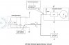
1. ~11 Vdc on the speed sensor power in wire (brown)
2. 4.75 or .27 Vdc on the speed sensor signal out wire (pink) as the rear wheel is rotated.
3. same alternating voltage indications at the back of the combination meter (pink/green and green wires)​
According to the service manual and the above symptoms the problem should be in the speedo. However, since this is an intermittent problem I might have been troubleshooting when it was "OK."

I don't really want to put out ~$700 for a new meter on the off chance that the problem is there. What is the chance that the sensor is failing? It "only" costs $75 from Ron Ayers. I see from several other threads that intermittent speedometer problems have happened to other people. What has been the fix: a bad meter or a bad sensor?

Thanks for everyone's help with this. Losing a speedometer isn't a big deal until "the Man" pulls me over...
 
Mine had a bent pin where the speedo's wiring harness connected to the speedo.

See the Honda Service manual, page 2-18. Pull-off the windscreen (4 screws, 4 bolts), then the front black plastic cowl. The cowl comes off by releasing the 8 trim clips on the top and front, and the 4 screws on the rider's side of the cowl. See page 22-12. Pull-off the black rubber boot, exposing the 20-pin and 16-pin wiring harnesses. The combination meter (speedo, etc.) is on the left (20-pin). Remove the 20-pin harness. Have a look down both the harness side and the speedo side of things where the pins mate to make sure that they do so completely.

Place the bike onto its center stand and start the engine. Put the bike into second gear and see what the speedo has to show. Wiggle the wiring harness between your fingers as you test. This may prompt your interruption.

Failing that, shut everything off. You're ready to use a multimeter to test as described on page 22-12. Again, be sure to wiggle the wiring harness as you test.

Marshal
 
Latest troubleshooting results:
Put the bike on the centerstand in 2nd gear and observed speedo while moving 16-pin connector and wiring - no effect. Speedo did drop to zero when (I think) I tapped on the sensor. Since I wasn't looking directly at it, it was tough to tell. Of course it wouldn't function again in the garage, so the only way to tell is to check it while operating

I've connected two extension wires to the back of the 16-pin connector (pink/green and green wires). This way I can check sensor output voltage while I'm riding. I just have to figure out how to keep my Fluke from flying off the bike. Wish I had a tank bag...
I'm not positive, but I'm pretty sure that the 16-pin connector is for the tach. The speedo and tach are not on the same bus.

Marshal
 
Check the condition of the wiring from the speed sensor at the engine up through where the connector is on the right side behind the canister. If the wires look good seperate the connector plug, make sure it is clean and then reassemble. It could be a wire that has broken or a dirty connection at one of the plugs.
 
The plot thickens

Just went to lunch while measuring the 16-pin connector pink/green wire voltage. Constant 4.7 Vdc no matter how slow I went - and no speedo indication. But did I measure the right wire? I traced the signal wire in the schematic to come up with pink/green, but might have made a mistake. That is the wire color on the wire harness side of the right side sensor connector. Unless there's another connector inbetween, it should be the same wire. Back to the service manual...

I did check the sensor connector and wiring (as much as I could see). No apparent problems.

BTW, try not to ride with a multimeter balanced between the handlebars.
 
Last edited:
Yet another reason to keep the 1100! :rofl1:

(Oh WAIT! ReSTored's odo is missing over 3000 miles in the last two seasons due to my ham-handed mechanic.)
 
If it's not on the odometer, then you didn't actually ride it.

Closing in on the problem. Riding home I measured 2.5 Vdc on the pink/green wire with the speedometer operating. While stopped at a light the voltage was either 4.7 Vdc or .3 Vdc. Confirmed that the combo meter is functioning correctly and confirmed that my print reading was accurate. Also, if the voltage goes high when the speedo fails then it can't be an open lead; and wires shorted together is even more unlikely.

The sensor has probably failed: I'm confident enough to order a new one. I should be able to install it sometime next week.
 
Last edited:
....Also, if the voltage goes high when the speedo fails then it can't be an open lead; and wires shorted together is even more unlikely..

David,
Actually, it could be an open lead.

I've attached a diagram, showing more details of the ST1300's Vehicle Speed Sensor (VSS) circuit. Although not 100% accurate, it touches on some of the more salient points.
The ST1300's VSS uses an open-collector-type output driver. There is a pull-up resistor, completing the circuit of the output driver, embedded in the Instrument cluster. If there is an open circuit (ie. broken wire) somewhere on the pink/green wire, anywhere between the sensor and the instrument cluster, then you will see a constant +5 vdc (or very near).

Bottom line... As long as you're sure there's no problems with broken harness wires, faulty connector pins, etc... I'd agree with your assessment, that the VSS is defective.
 

Attachments

  • VSS-Circuit.pdf
    44.5 KB · Views: 32
  • VSS-Circuit.jpg
    VSS-Circuit.jpg
    75.1 KB · Views: 89
Last edited:
Put another tap to the pink/green wire at the ECM and measure the difference between that one and the one by the instrument cluster. They normally would measure no difference unless a break in the wire appears. Looks like the wire runs through a 24 pin connector. Have you opened that up to look for any corrosion? Another point to check, although unlikely, would be the condition of the ground wire where it mates up to all of the other grounds underneath the fuel tank especially since yours is a 2003 model. One of the recalls during that year concerned the grounding bus.
 
I ordered the sensor but still have time to do more checks. Exactly where is the ground bus connection and the 24 pin connector?
 
The end of the story and some questions/lessons

Finally received the new speed sensor yesterday - 4 weeks backordered. Installation was pretty easy, but be aware that there's oil behind the sensor, which comes out when you remove the unit. The service manual doesn't mention this little fact. I drained about 1.4 quarts in the process of changing the sensor, luckily into a bucket and then back into the bike. After sensor replacement the speedometer/odometer worked fine: bike restored to full operation. Thumbs up.

Lesson learned: There's a reason the manufacturer uses O-rings, and it's not just for looks.

Question 1: I had changed the oil and filter <1000 miles/< 2 weeks ago (Castrol 10W-40). The oil I drained came out pretty dark already. Is this normal? How long does it take oil to look "dirty?"

Question 2: Along with the oil, not a small amount of metal flakes drained out of the sensor port. Since I had recently changed the oil this surprised me, but not in a nice way. Does the pan area behind the sensor normally drain during a standard oil change? Does anyone drop the oil pan to clean it out?
 
Back
Top Bottom