ADE
Has anyone done a hazard switch add on,on a 1100.

")
I know this post is over 9 years old, however, Uncle Phil, do you recall if there were more steps (after step 7) to the installation of the Honda hazard switch? I have the Honda hazzard switch and want to install it on my new bike. I have installed the 4 ways on my 97 and have used a generic switch and diodes, but this method looks simpler. ThanksThe US models don't come with it but as was said, it's an easy connection - just make sure you keep the left circuit and the right circuit separated so you your turn indicators don't both fire during normal use. There are also Honda Part numbers which include the hazard switch and the bezel for flashers. I used two simple relays (some used diodes) that fire from the same power source and triggered by the same switch. Since I have the left hand police switch, I used switch 5. Here's some instructions from another STer -
ST1100 4-Way Flasher Installation Instructions
The following instructions are meant to help aid the installation of a 4-Way Flasher setup on the Honda ST1100, 1990-2002. Information contained within this document is a collection of experience of my own installation and the installation of other ST1100 owners around the world. Please note, there are many ways to install a 4-Way Flasher setup, and this is just one of those. This design will allow the flashers to work without the switch being in the “ON” position, and requires that you use the Honda OEM waterproof pushbutton switch. The following is a list of part that I purchased for my installation.
Parts:
1) 35160-MZ9-900, the pushbutton for the flashers (button with red triangle)
2) 35180-MZ9-900, the pushbutton for the H/L Hazard button (headlight hazard)
3) 64227-MY3-780ZA, the bezel that surrounds the two buttons.
*This is the same bezel that is used for the TCS and ABS buttons on the ST1100A. (Note that the above three items were purchased from overseas. I have not found a US distributor for these as of yet.)
4) 2 PIN Flasher module, purchased at local auto parts store
5) 16 Gauge wire, approximately 8 feet, 3ft. for left side, 5ft. for right.
6) Inline fuse, 10 Amp
7) Wire splice units
1 2
3 4
5 6
Remove the Seat 1), the left saddle bag 2), the left side cover 3), and the left maintenance cover 4). You will also have to remove the rear view mirror covers on both sides of the bike 5). (They will pop off if you push them towards the front of the bike.)
You will want to locate a spot under the left fairing pocket to mount the switch setup. As you can see in picture 6), I mounted mine directly under the pocket as to not interfere with the fairing brackets and equipment located lower on that side of the bike. After the left maintenance cover is off, you can look and feel under the cover to see the best location to cut the hole. I used a Dremel to cut the hole after marking it clearly. You may want to use masking tape and a marker to get the best results. It took some time to line up and center the bracket. Remember the golden rule, measure twice, cut once.
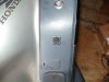
7
The wires for the Turn Signals/Marker Lights, come out of the main fairing and go directly into the rear view mirror covers 7). Locate the Orange/Gray (OG) wire on the left side and the Light Blue/Grey (LB) wire on the right side of the bike. You will tap into these wires which will control the front and rear lights for the bike. (You will not have to tap into wires at the front and rear of the bike, just the front.)
I don't know since I use the police switch and diodes. If the circuit 'separation' is built into the Honda hazard switch, then that should be about it.I know this post is over 9 years old, however, Uncle Phil, do you recall if there were more steps (after step 7) to the installation of the Honda hazard switch? I have the Honda hazzard switch and want to install it on my new bike. I have installed the 4 ways on my 97 and have used a generic switch and diodes, but this method looks simpler. Thanks
Thanks for your assistance, I have done a search for that post but have come empty handed.I don't know since I use the police switch and diodes. If the circuit 'separation' is built into the Honda hazard switch, then that should be about it.
That was the reason I decided to use number 5 on the police switch instead of the 'stock' switch - easy to press with the right thumb!It works fine, but I really don't like having to remove my hand from the handlebar to turn it on.
Thanks John, I have looked at that link a few times in the past, I now must confess, I now understand how he hooked up the switch.