Now
that's news you can use.
")
Thanks, Jim!
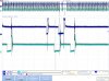
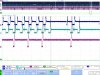
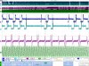
Probably not related to your problem but interesting: There's a small spike in the cyan trace when the coil is done firing and blue trace rises back to its charged state. It's hard to tell from the pictures if the opposite is happening because the cyan trace extends into the blue trace where it would be. There may be some crosstalk in the wiring and isn't anything to worry about. The injector trace gets a bit of it, too.
I still think this is being caused by one of the things that induces a no-start. If the sensors are off the table, the injectors are next. They appear to operate the same way as the coils, where the line is held normally high and pulled low when it's time to fire. The coils have to work that way to make spark, but the injectors may do it so the ECM can continuously monitor the circuit and kill the works if one goes south. (I have meetings all day today, but I'll check the manual later and see if I can figure out of that's correct.)
If Jim's willing to spend some more 'scope time with you, I'd instrument each of the injectors and watch for one misbehaving just before the misfire. You'll want to test both the supply and drain (ground) side of each, looking for a difference in the shape of the signals just before it happens. You should see some voltage difference across the injector, but if there's an intermittent open in the injector itself, the drain side will drop to zero before the ECM burps and doesn't fire the plugs/injectors. If you see a full drop of everything, you could have a wiring problem, and it would be worth repeating the test at the ECM end of the wiring harness.
One other idea from off in left field: If the FI indicator is driven by a single line from the ECM, probe that and see if it goes high briefly during the misfires. My thought here is that the lamp itself is incandescent and doesn't illuminate very quickly, so and this might at least give you some idea that the ECM thinks there's a fault. Won't tell you what the fault is, but at least it's another data point.
HTH.
--Mark