ST1100Y
Site Supporter
Can't tell that right away, as I'd never taken measures...Am I understanding this right; 12 V at the field (2P connector) should provide max output of the stator, or 0V on the 2P provides max output of the stator?
The rotor consists of permanent magnets, once it starts to rotate, the magnetic field lines get "cut" by the stator windings, thus induce voltage into them, etc...
This process takes place without auxiliary power applied... but I honestly don't know if voltage applied at the 2P "boosts" the field/output or "dampens/distorts" it...

Would need to crank up the '94 and check...
The w/shop manuals says 0~0,4Ohm between black & white of the alternator; probably depends on the voltage your voltmeter operates at (ohmic vs inductive resistance)...Also to confirm, the 3 Ohm resistance is on the Alternator side of the 2P connector (black and white wires).
")
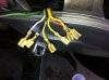
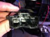
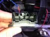
 :capwin::clap2: Replace ALL those connections.