
DakotaJoe
You can call me Scott
You have to be kind of handy to do this but instead of using the Centech AP-1 or the Eastern Beaver CP8 - Power Center 8 Fuse Boxes, I decided to make my own.
I did use the layout of the Power Center but mine only cost me around $30 to make and my wires were the length I needed to put it exactly where I wanted.
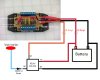
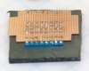
I started out with the wiring diagram (see picture) and bought the parts I needed from Radio Hut and on-line electronic parts stores. I did have to settle on the larger fuse clips but found out that the little fuses slide in to those too. (at your own risk)
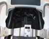
I also decided to place the unit under the rear seat in the square space with the weird rubber band. I dry fit the box and it looked like it would work for me. I used 16 gauge wire for most of the runs but used 14 gauge going to the relay and battery.
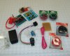
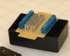
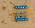
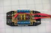
The PC board needed some cutting as it was not going to fit into the box I bought. I dry fit the blue wire connectors (I decided on 8 connectors) and put a fuse in the clips so I would know where to place those on the board.
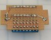
After putting in the parts, I flipped it over carefully on top of some hard rubber to hold them in place and soldered them onto the backside. (Sorry for the out of focus picture) I then used some computer motherboard mounting screws for attaching the wires. These are ideal because they can be soldered to the board because they are brass and they have a threaded inside so I can attach the wires.
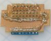
I used solder wick to run most of the connections underneath. This is braded copper wire that I bent to where I needed it and then I just ran solder along it for a very solid connection. I soldered together two of the positive side fuse clips to one mounting screw for the constant 12V power.
I used small bits of solid core copper to go from the negative side blue connectors to one side of the fuse clips for a good connection.
Then using the same solder wick technique, I soldered together the other six positive side fuse clips to the other mounting screw for the switchable 12V power and the negative side connectors. There was no worries to shorting things out underneath because the small copper circles do not connect but I did dremel them off between the two sets of switchable and constant positive fuse connectors.
I tried both the larger fuses that fit perfectly and the smaller fuses that are becoming more popular. They both worked fine so I used a mix of both sizes as that was what I had in my fuse bin.
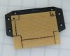
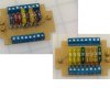
I hot glued the bottom to cover all the exposed connections. A bit of hot glue around the edges and the board was mounted to the black box plate. I dremeled out the box top to accommodate the wires coming in and going out. I would have loved having the Positive and Negative coming out of one side so the back would be able to rest on the bike without crushing wires, but I saw little room and a potential for wiring it wrong so I stuck with the standard spider leg design.
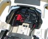
I put a 20Amp fuse between the block and the battery and a 30Amp fuse between the block and the relay. The relay came with 5 connectors and I only needed 4 so I took out the unused one. I followed the wiring diagram and put a diode in line just to make sure nothing came back through to the bike.
The relay attached very nicely behind the battery and I put a small hole in the back of the red rubber on the positive post to run my wires. I ran the red trigger wire from the relay coil to the rear marker light. -- Bike on, 12V on--. I wanted at least two auxiliary outlets on all the time in the event I was charging a phone or something and I left the bike for a bit. You can also use those for an alarm system.
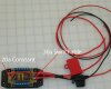
I left enough wire from and to everything so that I could pull out the fuse box and hook up other things without ripping off a connector. I took a last picture of how it looks all tucked away and I was very happy with the end result.
As with all my modifications, try them at your own risk. It works for me, I hope it works out for you if you give it a try. Please check out my albums for more pictures on this and other modifications.
I did use the layout of the Power Center but mine only cost me around $30 to make and my wires were the length I needed to put it exactly where I wanted.
I started out with the wiring diagram (see picture) and bought the parts I needed from Radio Hut and on-line electronic parts stores. I did have to settle on the larger fuse clips but found out that the little fuses slide in to those too. (at your own risk)
I also decided to place the unit under the rear seat in the square space with the weird rubber band. I dry fit the box and it looked like it would work for me. I used 16 gauge wire for most of the runs but used 14 gauge going to the relay and battery.
The PC board needed some cutting as it was not going to fit into the box I bought. I dry fit the blue wire connectors (I decided on 8 connectors) and put a fuse in the clips so I would know where to place those on the board.
After putting in the parts, I flipped it over carefully on top of some hard rubber to hold them in place and soldered them onto the backside. (Sorry for the out of focus picture) I then used some computer motherboard mounting screws for attaching the wires. These are ideal because they can be soldered to the board because they are brass and they have a threaded inside so I can attach the wires.
I used solder wick to run most of the connections underneath. This is braded copper wire that I bent to where I needed it and then I just ran solder along it for a very solid connection. I soldered together two of the positive side fuse clips to one mounting screw for the constant 12V power.
I used small bits of solid core copper to go from the negative side blue connectors to one side of the fuse clips for a good connection.
Then using the same solder wick technique, I soldered together the other six positive side fuse clips to the other mounting screw for the switchable 12V power and the negative side connectors. There was no worries to shorting things out underneath because the small copper circles do not connect but I did dremel them off between the two sets of switchable and constant positive fuse connectors.
I tried both the larger fuses that fit perfectly and the smaller fuses that are becoming more popular. They both worked fine so I used a mix of both sizes as that was what I had in my fuse bin.
I hot glued the bottom to cover all the exposed connections. A bit of hot glue around the edges and the board was mounted to the black box plate. I dremeled out the box top to accommodate the wires coming in and going out. I would have loved having the Positive and Negative coming out of one side so the back would be able to rest on the bike without crushing wires, but I saw little room and a potential for wiring it wrong so I stuck with the standard spider leg design.
I put a 20Amp fuse between the block and the battery and a 30Amp fuse between the block and the relay. The relay came with 5 connectors and I only needed 4 so I took out the unused one. I followed the wiring diagram and put a diode in line just to make sure nothing came back through to the bike.
The relay attached very nicely behind the battery and I put a small hole in the back of the red rubber on the positive post to run my wires. I ran the red trigger wire from the relay coil to the rear marker light. -- Bike on, 12V on--. I wanted at least two auxiliary outlets on all the time in the event I was charging a phone or something and I left the bike for a bit. You can also use those for an alarm system.
I left enough wire from and to everything so that I could pull out the fuse box and hook up other things without ripping off a connector. I took a last picture of how it looks all tucked away and I was very happy with the end result.
As with all my modifications, try them at your own risk. It works for me, I hope it works out for you if you give it a try. Please check out my albums for more pictures on this and other modifications.
Attachments
-
 255.5 KB Views: 355
 -
 438 KB Views: 224
 -
 386.1 KB Views: 194
 -
 325.6 KB Views: 113
 -
 290.7 KB Views: 170
 -
 449.7 KB Views: 367
 -
 370.1 KB Views: 180
 -
 308.8 KB Views: 144
 -
 405.9 KB Views: 136
 -
 445.8 KB Views: 249
 -
 334.2 KB Views: 160
 -
 387.6 KB Views: 190
 -
 226.9 KB Views: 224
Last edited by a moderator: