
After looking at several ideas, I liked the concept of the remote transmitter
being securely locked away in the left glove box. And I liked having a
separate hard-wired button to activate the opener, and having the button
in a spot where I wouldn?t have to take my hands off the bars when I
approach the garage. And I did not want to take any plastic body panels
off during the project.
I decided to put the button on the right switch housing and run the wires
down the right handlebar and across to the left glove box. This proved to
be more difficult than simply putting the button next to the glove box, but
much easier to access. And the installation is inconspicuous and clean.
I also wanted some kind of simple connection somewhere in the middle of
the wire that would allow me to take off the left body panel with the
pocket and opener still inside without having to cut and re-splice the wires
every time.
Components Neededbeing securely locked away in the left glove box. And I liked having a
separate hard-wired button to activate the opener, and having the button
in a spot where I wouldn?t have to take my hands off the bars when I
approach the garage. And I did not want to take any plastic body panels
off during the project.
I decided to put the button on the right switch housing and run the wires
down the right handlebar and across to the left glove box. This proved to
be more difficult than simply putting the button next to the glove box, but
much easier to access. And the installation is inconspicuous and clean.
I also wanted some kind of simple connection somewhere in the middle of
the wire that would allow me to take off the left body panel with the
pocket and opener still inside without having to cut and re-splice the wires
every time.
- garage door opener with large circuit board
- 6ft of doorbell wire
- 6 inch strip of self stick two-sided Velcro
- Radio Shack switch 275-644
- Radio Shack 1/8 mono jack 274-333
- Radio Shack 1/8 mono plug 274-286
- wire strippers
- heat shrink tubing
- stubby step drill for ? inch hole
- Philips screwdriver
- black electrical tape
Installation
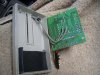
- Remove circuit board from opener.
- Using a multi-meter, locate two contacts on the back of the board
that will activate the opener. - Solder 2ft of wire to contact points
- Install battery and test circuit by touching ends of new wires.
- Drill hole in opener for wire, and put circuit back inside, and close it up.
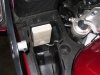
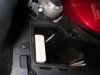
- Stick Velcro on back of opener and in upper, front area of pocket.
Position opener in pocket.
- Remove door if necessary, and drill hole in upper right area of pocket for wire.
- Feed wire through to front area of gas tank. This part of the install is done.
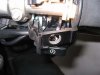
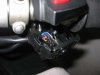
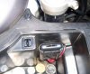
- To open the right switch housing, loosen the throttle cable adjuster
as much as possible, and remove the two lower screws. - Using a small screwdriver, remove the two small metal plates
covering the wiring inside the lower part of the housing. - Remove the little square plastic block that protects the wire bundle
under the metal plate. - Using the step drill, make a ? inch hole exactly in the middle of the
flat area of the lower switch housing.
- Clean up the hole and test fit the switch.
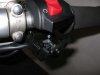
- Pull out the switch, solder 4ft of wire to the leads, and wrap the
exposed fittings with tape or tubing. - Run the wire through the hole, through the plastic nut, and out the
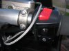
housing along side the wire bundle. - Seat the switch and tighten the nut.
- Without pinching wires, replace the little plastic block and two metal plates.
- Close up the switch housing. Tie the new wire along side the big
bundle back to the frame near the right front area of the gas tank.
This part of the install is done.
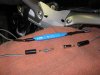
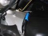
- Cover the tank with a thick blanket, and lay out the two wires and
the connector pieces. Cut the excess wire, but leave about 6 inches
extra per side for slack. - Solder the connectors to the wires, and wrap well to keep out water.
- Now you must raise the tank to hide the connector. Pull off the seat.
Move the front seat bracket back to the maintenance position.
Loosen the long rear 10mm tank bolt. Remove the front two 8mm
bolts, being careful to not drop the washers or spacers into the gap.
Raise the tank up using the supplied prop rod under the seat. - With the tank up, you can lower the new connector down in front of
the air filter box. It will lay there, protected by the frame. - Zip-tie the wires on the right and left sides to the frame studs and
existing wire bundles, but leave enough slack to get the connector
out later if you need to disconnect it to remove body panels for
future projects.
- Lower the tank. Re-install the seat. And turn the bars lock to lock to
make sure the wires have enough slack and aren?t being pinched. - Go for a test ride.
Conclusion
I think you will find that the new opener button mounted on the right bar is
extremely convenient and much safer than fumbling around for the opener
in the glove box while trying to downshift and brake as you enter the driveway.
I think you will find that the new opener button mounted on the right bar is
extremely convenient and much safer than fumbling around for the opener
in the glove box while trying to downshift and brake as you enter the driveway.
Attachments
Last edited by a moderator:

")