Article [13] ST1300 - Maintenance - Front & Rear Wheel Install and Front Axle Animation

Another great "save your butt" article!
The last associated front fork PITA I've done was my V65 Magna. The ST is generations removed from that.
Thank you. I had to change the front tire on it just yesterday (used bike purchase). Got it all in right, but have lots of new-pad drag. I'll loosen up the axle and do these steps again. MUCH better than the cryptic manual, for sure!

Thank you.
 
Thanks to all for the advice. I have to change the rear wheel on my new to me bike for the first time. This article and additional input provide me with the information and confidence to at least try to change it myself.
 
I am maybe missing something obvious or just not understanding the purpose of the process.

Bounce the fork.jpg

I have been watching this a hundred times and I still can't understand the logic.
How can you modify the alignment of the wheel when:
- the right side of the axle clamp on the right fork leg shoulder stop and the right spacer and then the bearing on the hub shoulder
- the left side of the axle have a shoulder pushing on the wheel spacers and the left bearing
I don't see any play possible or the wheel being able to move laterally in any direction?
The only thing I see able to move laterally is the left fork leg axle support from the vertical play of the tube, not the wheel.
Were is the variable or possible play?
 
It is to make sure that everything is settled into its proper position

The axle which is clamped to the right fork leg, can be twisted slightly in relation to the left hand fork leg, or the fork legs can be strained slightly - think of the fork leg as a separate component and it is secured to a fixed axle by its pinch bolts. the fork leg is in an upright position, not attached to anything else. The axle is held firmly . It cannot move. Now imagine pushing on the top of the fork leg - trying to move it like a clock hand from the 12 oclock position. You will have some success. Some reasons:

The axle will twist slightly. Yes, metal bars will twist. Think torsion bar suspension, beam type torque wrenches
The moving parts will exhibit some 'play'
The fork leg and tube will bend slightly.
Fork legs were not facing quite the same way - one is pressing on the back of the axle, the other on the front.
Fork legs were not quite level - one pressing on the top of the axle one on the bottom

Those tiny misalignments could be locked in place by friction and the weight of the motorcycle.

As soon as you clamp the left fork leg, the tiny misalignments are locked in place - so before you do that, you bounce the forks a few times to help the components to settle into a more relaxed position. To overcome the friction and take the weight off the front wheel momentarily.

Have you ever seen a motorcyle after a drop. Forks and wheel seem to be twisted, but sometimes they are not damaged. The forks have twisted in their tubes, the axle has rotated on one side, and one fork has compressed more than the other. And the tubes have twisted in the yoke. All that needs to be done is for everything to be undone, rearranged and tightened up again

You must have got on mechanical weighing scales, looked down and thought - thats not right. So you get off and try again. Or you put a foot in the scales and take it off quickly to make sure that the mechanism is free to move. Then you try again and all is well with the world. It shows the correct reading.

What you are doing with the scales is exactly what you do when bouncing the forks. Freeing things up making sure that they are moving properly, before applying the final securing bolts to lock the settings into position.

Now if only weighing scales had such a locking device ...

 
Last edited:
It is to make sure that everything is settled into its proper position

The axle which is clamped to the right fork leg, can be twisted slightly in relation to the left hand fork leg, or the fork legs can be strained slightly - think of the fork leg as a separate component and it is secured to a fixed axle by its pinch bolts. the fork leg is in an upright position, not attached to anything else. The axle is held firmly . It cannot move. Now imagine pushing on the top of the fork leg - trying to move it like a clock hand from the 12 oclock position. You will have some success. Some reasons:

The axle will twist slightly. Yes, metal bars will twist. Think torsion bar suspension, beam type torque wrenches
The moving parts will exhibit some 'play'
The fork leg and tube will bend slightly.
Fork legs were not facing quite the same way - one is pressing on the back of the axle, the other on the front.
Fork legs were not quite level - one pressing on the top of the axle one on the bottom

Those tiny misalignments could be locked in place by friction and the weight of the motorcycle.

As soon as you clamp the left fork leg, the tiny misalignments are locked in place - so before you do that, you bounce the forks a few times to help the components to settle into a more relaxed position. To overcome the friction and take the weight off the front wheel momentarily.

Have you ever seen a motorcyle after a drop. Forks and wheel seem to be twisted, but sometimes they are not damaged. The forks have twisted in their tubes, the axle has rotated on one side, and one fork has compressed more than the other. And the tubes have twisted in the yoke. All that needs to be done is for everything to be undone, rearranged and tightened up again

You must have got on mechanical weighing scales, looked down and thought - thats not right. So you get off and try again. Or you put a foot in the scales and take it off quickly to make sure that the mechanism is free to move. Then you try again and all is well with the world. It shows the correct reading.

What you are doing with the scales is exactly what you do when bouncing the forks. Freeing things up making sure that they are moving properly, before applying the final securing bolts to lock the settings into position.

Now if only weighing scales had such a locking device ...

I always took literally the notion of "front wheel alignment" and there is not a such thing on the ST. The right hub shoulder/bearing is the only absolute centering point and there is no optional way to modify it. If I now understand the mounting process correctly, it is more a structural alignment of the front end.
Thank you so much for taking the time for answering my question.
 
Very good info. Recently purchased my first ST1300 and it needs both front and rear tires. Ordered tires but stealership wants an arm and a leg to install so I'm going to do it myself. I have more time than money sort of speak and at least I will know that it's done right.
I’m in the same boat this year (this week in all likeliness). Did it go smoothly ? LMK if there’s anything particular to watch out for since I’ve not done this on the ST1300 before.
 
I always took literally the notion of "front wheel alignment" and there is not a such thing on the ST. The right hub shoulder/bearing is the only absolute centering point and there is no optional way to modify it. If I now understand the mounting process correctly, it is more a structural alignment of the front end.
Thank you so much for taking the time for answering my question.
Yes - I suppose so. But if you get it wrong, the wheel ends up out of alignment. 'Alignment' is a state, not a process like turning an adjusting screw.

There are things that you do when installing the front wheel to make sure that the wheel isn't installed out of alignment - but I have covered most of these already. The one that is often not understood is the correct order for installing the bearings - because only one bearing is driven up against a shoulder in the hub. The other isn't - and it matters which one you put in first.

But they don't jump out and switch sides overnight when you are not looking. (Unlike some of my tools).
 
Last edited:
I lightly smear the axle just to prevent corrosion. It doesn't move and nothing it is in contact with moves so it isn't for lubrication.
 
Is axle grease required ? I don’t see anyone mentioning it.
Covered in Honda's standard operating procedures which states;
Coat the axle shaft with a small amount of grease.

It doesn't state what kind of grease but that isn't critical as the main purpose of the grease is to prevent corrosion, not to provide lubrication.
My recommendation would be any rubber safe water-proof grease, such as automotive wheel bearing grease.
 
Covered in Honda's standard operating procedures which states;
Coat the axle shaft with a small amount of grease.

It doesn't state what kind of grease but that isn't critical as the main purpose of the grease is to prevent corrosion, not to provide lubrication.
My recommendation would be any rubber safe water-proof grease, such as automotive wheel bearing grease.
Perfect. Thanks.
 
Animated sequence to show the correct procedure when installing the front wheel into the forks of a Honda ST1300.

The right hand side of the bike is the side with the brake lever. Left is the clutch lever side. This is the convention used in the Honda manuals.​
The video and the photo below are both shown as if looking at the front wheel from in front of the bike. So the brake lever side of the bike is on the left of the image.​


The spacers that sit between the fork and the wheel hub can be fitted in 4 different ways, only one of which is correct. The other 3 will cause damage.
Mine are easy to spot from the polishing of the dust seals on the spacer - but beware using similar marks if your bike was bought second hand !

1596319614345.jpeg

Below are two pdf documents on installing the front wheel and rear wheel respectively.
(Just updated 1 Aug 2020) - 57 downloads of previous versions)

------------------------------------------------------------------------------

Other related articles:

Article13.png ST1300 - Fitting Wheel Bearings - What the manuals don't tell.
Article13.png ST1300 - Front wheel bearing replacement [VIDEO]


------------------------------------------------------------------------------
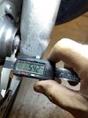
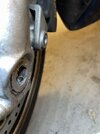
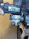
Hi Guys, I've just installed my front wheel after a tyre change and it seems to be OK but I want to verify. The Left side of the bike (as per picture provided by Jheath ) doesn't gel with what I've found (IMG_1133). The diagram given says 4mm whereas I measure a lot more and it goes inward (recesses) I've attached my pictures. As you can see the Left side picture shows the shoulder to be 5.4mm from the wheel axle surface (Non ABS 2003 ST1300). I tried turning this around but it causes the Brake Disk to rub the support strut. When I turned it around it made clearance and the wheel ran free. I was then able to install the brake calipers and lock them in place and they seem to seat well. The wheel turns but has a small amount of resistance once I tightened the axle nut/hex to spec torque (I've lubed everything including bearings). The brakes seem to clamp down correctly.


My concern is that the 4mm given in the diagram does not meet what I measure. Do I have this in backwards ? Does the left Hex need to seat more to take up this slop (IMG_1136) ? .

I'd like to get confirmation (or correction) before I take it on a test run since I don't want to damage anything.

Thanks.
 

Attachments

  • IMG_1132.jpg
    IMG_1132.jpg
    123 KB · Views: 28
  • IMG_1133.jpg
    IMG_1133.jpg
    143.6 KB · Views: 29
  • IMG_1136.jpg
    IMG_1136.jpg
    85.2 KB · Views: 27
  • IMG_1137.jpg
    IMG_1137.jpg
    151.8 KB · Views: 23
  • IMG_1138.jpg
    IMG_1138.jpg
    149.9 KB · Views: 23
Last edited:
I don't see the left spacer in your photos, is it intentional for the purpose of measurement?
If present, it looks like seating surprisingly deep in the hub.

1724730769099.png
 
Last edited:
Hi Guys, I've just installed my front wheel after a tyre change and it seems to be OK but I want to verify. The Left side of the bike (as per picture provided by Jheath ) doesn't gel with what I've found (IMG_1133). The diagram given says 4mm whereas I measure a lot more and it goes inward (recesses) I've attached my pictures. As you can see the Left side picture shows the shoulder to be 5.4mm from the wheel axle surface (Non ABS 2003 ST1300). I tried turning this around but it causes the Brake Disk to rub the support strut. When I turned it around it made clearance and the wheel ran free. I was then able to install the brake calipers and lock them in place and they seem to seat well. The wheel turns but has a small amount of resistance once I tightened the axle nut/hex to spec torque (I've lubed everything including bearings). The brakes seem to clamp down correctly.


My concern is that the 4mm given in the diagram does not meet what I measure. Do I have this in backwards ? Does the left Hex need to seat more to take up this slop (IMG_1136) ? .

I'd like to get confirmation (or correction) before I take it on a test run since I don't want to damage anything.

Thanks.
Reading the manual I think I have the left collar (as you sit on the bike) the wrong way around. However when I install that way round the disk rubs the steering column strut. Is this just a case of getting the axle seated correctly and it’ll space things out ? Will play with it tomorrow and see.
 
Last edited:
I don't see the left spacer in your photos, is it intentional for the purpose of measurement?
If present, it looks like seating surprisingly deep in the hub.

1724730769099.png
I think the left spacer )as you sit on the bike) is in backwards. In the shop manual it’s referred to as a collar. I have no other parts so there is no spacer or extra things that I’ve missed. The only thing I can think of is that the hexnut side of the axle (left) has to seat in further to get the correct spacing. Will try this in the morning.

The big issue I have is I can't read the shop manual when my hands are laden with grease and I need to turn a page!!
 
The photo shows the axle. On the axle is the right spacer/collar and the left spacer/collar. At the left end of the axle (right hand end of the photo) you can just see the shoulder which is essential for drawing all of the parts together. When assembled the left spacer/collar will sit tight against that shoulder. Apologies for not using the correct term 'collar'.

The point of the photo was to enable you to distinguish between the two collars and recognise which collar goes on which side. Without having to get out a caliper !

Put them on a worktop . Both collars have one side that is 10mm ish. Put that face down. Put side by side the flanges should touch be at the same height. 10mm off the work bench. That 10mm side fits against the bearing.

The end if each collar is easy to distinguish - one is 4x bigger than the other 4mm v 16mm. The taller one fits on the axle bolt (right / brake lever ) side, with the 10.1 mm half fitting into the seal, against the face of the bearing.

Your photos. Difficult to tell, but 1132 looks as though that is a 10mm side that I can see. It certainly isnt a 4mm side.
1136 reveals that the axle bolt is protruding out of the axle bolt hole. This suggest that you might have tightened the pinch bolts before everything was aligned - which might mean that when you tightened the axle bolt, the pich bolts were stopping the axle from being pulled across.

Take you wheel out. Take the collars out. Find out which is the left and which is the right. Put the 10mm side into the wheel hub held in place by the seal.
Put the wheel back and slide the axle through. Do not tighten any pinch bolts.

Watch the video. Note that the axle has a step on the left / clutch side. As the axle bolt is tightened, that step meets the left collar and moves it across to meet the left bearing (this is on the right hand side of the video screen). As the axle bolt is tightened more, look at the left side of the video screen. There is a big red arrow on the axle. Watch how the axle pulls across the entire hub so that the right / brake lever side bearing meets the right collar. The entire wheel assembly is then drawn tight against the right / brake lever side fork leg.

At this point the left / clutch lever fork legs has absolutely nothing to do with clamping the wheel. It is merely supporting that end of the axle. In fact the fork leg can move side to side on the axle with the wheel hub clamped firmly in place against the right hand fork leg.

Of course practicalities creep in. If you do not have a large hex driver, then you have to stop the axle from turning somehow. So when you push the axle in, make sure that you press it in firmly so that the end of the axle is almost flush with the fork leg. Then temporarily tighten the left / clutch side axle pich bolts. Then tighten the axle, then tighten the right axle bolt side pich bolts slacken the left / clutch lever pinch bolts again.

Your photo 1136 suggests that at least some of this process wasn't followed. I cannot see the flange on that photo, but it looks as though it has the shiny marks where the collar has been polished previously by the rubber seal. If the axle is tight it might also mean that you may have damaged the seal as it may have been squashed against the bearing. Maybe not if you tightened the axle with the left/clutch side pinch bolts tightened.

The next step is to fit the brakes, because you need to bounce the forks up an down while the brakes are applied. Then the left fork leg needs to be positioned so that the end if the axle is flush. If this isn't the case, as in your photo 1136, then your brake caliper which is now part of the left fork, will be pushed towards the brake disc/rotor and your brakes will bind, which will then apply the rear brakes. You need clearance between the point where the rotor passes through a narrow slot in the caliper bracket. See owners manual

Your photos 1137 and 1138 show the correct collar the correct way round. I cannot tell if the distance you are measuring is the same as the collar measurement. I don't recall whether the fork leg on the inside has a raised part of the moulding. They often do this for cast alloy - Cast a raised part so that it can be machined accurately to provide a smooth face at the correct 'height'.

Or maybe I measured incorrectly when I labelled the diagram. I only used a steel rule. I'll add a bit to the caption for that photo.

.
 
Last edited:
Back
Top Bottom