What I wanted:
To see (both far ahead as well as to the side).
For the lights to be stable, and not vibrate.
For them to be tucked in close to the bike, rather than stick out to the top or sides.
For the whole package to be inexpensive, attractive, and reliable.
Background:
I have used PAR36 landing light bulbs for many years in the past. They are bright, punch a spot way down the road, and have a nice scatter out to 180 degrees to help with the shoulder and ditch as well.
They come in a wide variety of wattages and patterns; the H7604 uses 50W, puts out 100,000 candlepower, and has a spot pattern 7 degrees wide by 5 high.
In the past, I have used the rubber utility light housings as they are cheap and readily available.
I do not like them, however, as they are neither attractive nor aerodynamic, and flex enough that the light beam vibrates all over the place regardless of how rigidly they are mounted.
Design
There are several very nice machined brackets designed for the ST. However, these are mostly specific for a certain light, and generally hang down farther below the mirrors than I like. So, I took the general idea and designed my own brackets to put my lights where I wanted them.
To do this, I took the mirror shells off, then took a bunch of pictures from various angles of the mirror bracket (with a small ruler in the picture to get scale from). I also made a template from heavy paper of the various angles of the bodywork.
I then took all this information and made a CAD drawing of what I thought would work. I then made a prototype, put it in place, and measured where it actually was. I then adjusted the CAD drawing to put it all where I wanted it to be.

Supplies
The light housings are from Truck-Lite (even though Signal Stat is stamped into them; apparently Signal Stat were bought out by them some years ago).

Truck-Lite
Unfortunately, these are not perfect for this application. With the ST mirror mount, the bracket angles back a bit, so the light needs to angle forward on it's pivot. The collar with these housings (concave spherical part) is wide enough that the light beam cannot be less than 90 degrees from the mounting bolt. Also, that collar is huge (~1-1/2" diameter), and being stamped steel would make a nice bucket to guide water down inside the housing. To remedy both these factors I found some stainless spherical washers at McMaster. The female-only part (concave) is part number 94007A214. These have an outside diameter of 24mm, which fits nicely on the 1" brackets.
The next complication is that the shoulder of the mounting bolts is larger than the ID of the new spherical washers. So, I chucked the bolts in the drill press and used a file to reduce the part of the shoulder that interfered. I left a bit next to the head alone, as that is what keys into the housing to keep the bolt from turning as you tighten the nut.

I also drilled a hole through the bolt, so that I could run the power wires internally. Make sure you chamfer the top and bottom of this hole, or it can cut through the insulation and cause a short.

In the same order from McMaster, I got some M6x70 stainless socket head cap screws to go through the light brackets and mirror brackets (pn 91292A202).
I actually purchased 1"x3" aluminum bar, although when the design was finalized, I could have used 1"x2". The aluminum came from Online Metals
Fabrication
I have available a drill press, a Bosch jig saw, a grinder, and a sander. The best blades I could find for cutting thick aluminum are the T123; they are rated to cut 3/4" thick, but by gently rocking the saw slightly forward and backward they did quite well (it helps to have a bit of cutting oil too).
You can do a much nicer job if you have available a bandsaw and milling machine.
First, lay out and cut your bar so that you get a piece 2"x3".

I had 3" wide bar; you can be a bit more efficient with your materials if you get 2" wide.
Next, lay out the two 1/2" holes that will be the inside corners of the Z-shape. You don't want sharp inside corners, especially here, as any vibration can start a crack. Scribed marks are more durable than pencil (even though they don't show up too well in the picture).

Then, center-punch the holes so that the drill doesn't try so hard to wander.

Next, drill smaller diameter pilot (starter) holes. I used a 3/16" drill in this case.

Then, drill the large diameter holes (1/2"). Here, you really need to be careful that the drill doesn't catch the work piece and throw it at you. It can actually break bones (and bits) if this happens.

Now, things get a bit more tedious. You need to mark the four lines that you will cut. Make sure you don't get your corners mixed up; one wrong cut can scrap the part and you will have to start over. Also, when laying out and making these cuts, make certain that you do not get on the wrong side of the line. If the cut stops outside the radius, it will leave a sharp edge that can propagate cracks. If the cut stops inside the radius, however, it just leaves an angled edge instead of smooth, and can easily be smoothed out.


It's nicer to handle if you smooth everything out now. I also rounded the inside corners for relief at the fairing (there was a small bit of interference).

Next, drill the two holes (6mm for the mounting bolt, 1/2" for the housing bolt). Lay out, center punch,and drill each one.

Now it gets real tedious. The inside of the mirror bracket varies from .88" to .94". That is on mine; since these are unfinished castings they might vary more from bike to bike. You now need to file/grind/sand the edges so that the bracket will fit inside the existing mirror bracket. I scribed a mark .070" from each edge to use as a guide while working on this.

Eventually, it fits in where it is supposed to, and you can move on to cutting the mirror shell. One disadvantage to tucking the light in tight like this is that I will have to make a much larger cut into the mirror shell (~1"x2"). First, with the shell off, extend lines down from the bracket onto the fairing right below the mirror.

Then, remove the bracket, install the mirror shell, and extend the marks onto the shell.

Then, screw up your nerves and cut the shell. I used a scroll (curve-cutting) blade in the same jig saw. I also used tape to protect the mirror shell, and wiped all the crud off the bottom of the saw. Here, you want to cut on the outside of the line, to give just a bit extra room for installing the shell. It might take a bit of fussing with a file or Dremel to get to this point:

Electrical
You've got to get power to the lights somehow. The quartet harness doesn't supply enough current to reliably run these, so you need to tap in to the battery somehow.
Since I intend to add a few more things (heat, especially) I chose to mount an auxiliary fuse block near the battery. Here's the one I found at Advance Auto:

I thought it might fit just below the driver's portion of the seat, so I taped it in place, stuck some brittle foam on top, and put the seat on in the lowest position. Checked things out, and there was a little bit of clearance, so... I drilled into the inner fender, added a pair of threaded inserts, and stuck it on. The screws are M4x30.

Then, I ran a heavy fused wire to the battery, and now I don't have to disconnect the battery any more except to change it. The exposed spade terminals are not hot unless a fuse is in place. You need to use insulated terminals to connect to this. Put a bit of electrical tape or shrink tube over the main screw threads to prevent anything from shorting out with it.
From the fuse block, I ran a heavy wire up to a relay near the windshield. The relay is at the bottom of this picture; the two green/yellow wires at the top are ground for the switch and relay. Keep all the wires out of the way of the windshield travel, and make sure they are bundled so they don't flop around and rub holes in the insulation.

I put my switch on the dash shelf, quickly making a bracket from some scrap 1/16" aluminum angle that was laying around. The red LED iluminated switch also came from Auto Zone. I fastened the bracket to the shelf with M4 flat head screws and threaded inserts.


The RAM mount parts for my GPS mount came in today; here's how the switch looks installed:

Results
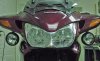
Here's how a light looks up close:

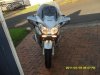
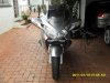
Here's how they look from the front:

The results can be seen in the beam spread pictures in the first post of this thread https://www.st-owners.com/forums/showthread.php?t=71049
To see (both far ahead as well as to the side).
For the lights to be stable, and not vibrate.
For them to be tucked in close to the bike, rather than stick out to the top or sides.
For the whole package to be inexpensive, attractive, and reliable.
Background:
I have used PAR36 landing light bulbs for many years in the past. They are bright, punch a spot way down the road, and have a nice scatter out to 180 degrees to help with the shoulder and ditch as well.
They come in a wide variety of wattages and patterns; the H7604 uses 50W, puts out 100,000 candlepower, and has a spot pattern 7 degrees wide by 5 high.
In the past, I have used the rubber utility light housings as they are cheap and readily available.
I do not like them, however, as they are neither attractive nor aerodynamic, and flex enough that the light beam vibrates all over the place regardless of how rigidly they are mounted.
Design
There are several very nice machined brackets designed for the ST. However, these are mostly specific for a certain light, and generally hang down farther below the mirrors than I like. So, I took the general idea and designed my own brackets to put my lights where I wanted them.
To do this, I took the mirror shells off, then took a bunch of pictures from various angles of the mirror bracket (with a small ruler in the picture to get scale from). I also made a template from heavy paper of the various angles of the bodywork.
I then took all this information and made a CAD drawing of what I thought would work. I then made a prototype, put it in place, and measured where it actually was. I then adjusted the CAD drawing to put it all where I wanted it to be.
Supplies
The light housings are from Truck-Lite (even though Signal Stat is stamped into them; apparently Signal Stat were bought out by them some years ago).
Truck-Lite
Unfortunately, these are not perfect for this application. With the ST mirror mount, the bracket angles back a bit, so the light needs to angle forward on it's pivot. The collar with these housings (concave spherical part) is wide enough that the light beam cannot be less than 90 degrees from the mounting bolt. Also, that collar is huge (~1-1/2" diameter), and being stamped steel would make a nice bucket to guide water down inside the housing. To remedy both these factors I found some stainless spherical washers at McMaster. The female-only part (concave) is part number 94007A214. These have an outside diameter of 24mm, which fits nicely on the 1" brackets.
The next complication is that the shoulder of the mounting bolts is larger than the ID of the new spherical washers. So, I chucked the bolts in the drill press and used a file to reduce the part of the shoulder that interfered. I left a bit next to the head alone, as that is what keys into the housing to keep the bolt from turning as you tighten the nut.
I also drilled a hole through the bolt, so that I could run the power wires internally. Make sure you chamfer the top and bottom of this hole, or it can cut through the insulation and cause a short.
In the same order from McMaster, I got some M6x70 stainless socket head cap screws to go through the light brackets and mirror brackets (pn 91292A202).
I actually purchased 1"x3" aluminum bar, although when the design was finalized, I could have used 1"x2". The aluminum came from Online Metals
Fabrication
I have available a drill press, a Bosch jig saw, a grinder, and a sander. The best blades I could find for cutting thick aluminum are the T123; they are rated to cut 3/4" thick, but by gently rocking the saw slightly forward and backward they did quite well (it helps to have a bit of cutting oil too).
You can do a much nicer job if you have available a bandsaw and milling machine.
First, lay out and cut your bar so that you get a piece 2"x3".
I had 3" wide bar; you can be a bit more efficient with your materials if you get 2" wide.
Next, lay out the two 1/2" holes that will be the inside corners of the Z-shape. You don't want sharp inside corners, especially here, as any vibration can start a crack. Scribed marks are more durable than pencil (even though they don't show up too well in the picture).
Then, center-punch the holes so that the drill doesn't try so hard to wander.
Next, drill smaller diameter pilot (starter) holes. I used a 3/16" drill in this case.
Then, drill the large diameter holes (1/2"). Here, you really need to be careful that the drill doesn't catch the work piece and throw it at you. It can actually break bones (and bits) if this happens.
Now, things get a bit more tedious. You need to mark the four lines that you will cut. Make sure you don't get your corners mixed up; one wrong cut can scrap the part and you will have to start over. Also, when laying out and making these cuts, make certain that you do not get on the wrong side of the line. If the cut stops outside the radius, it will leave a sharp edge that can propagate cracks. If the cut stops inside the radius, however, it just leaves an angled edge instead of smooth, and can easily be smoothed out.
It's nicer to handle if you smooth everything out now. I also rounded the inside corners for relief at the fairing (there was a small bit of interference).
Next, drill the two holes (6mm for the mounting bolt, 1/2" for the housing bolt). Lay out, center punch,and drill each one.
Now it gets real tedious. The inside of the mirror bracket varies from .88" to .94". That is on mine; since these are unfinished castings they might vary more from bike to bike. You now need to file/grind/sand the edges so that the bracket will fit inside the existing mirror bracket. I scribed a mark .070" from each edge to use as a guide while working on this.
Eventually, it fits in where it is supposed to, and you can move on to cutting the mirror shell. One disadvantage to tucking the light in tight like this is that I will have to make a much larger cut into the mirror shell (~1"x2"). First, with the shell off, extend lines down from the bracket onto the fairing right below the mirror.
Then, remove the bracket, install the mirror shell, and extend the marks onto the shell.
Then, screw up your nerves and cut the shell. I used a scroll (curve-cutting) blade in the same jig saw. I also used tape to protect the mirror shell, and wiped all the crud off the bottom of the saw. Here, you want to cut on the outside of the line, to give just a bit extra room for installing the shell. It might take a bit of fussing with a file or Dremel to get to this point:
Electrical
You've got to get power to the lights somehow. The quartet harness doesn't supply enough current to reliably run these, so you need to tap in to the battery somehow.
Since I intend to add a few more things (heat, especially) I chose to mount an auxiliary fuse block near the battery. Here's the one I found at Advance Auto:
I thought it might fit just below the driver's portion of the seat, so I taped it in place, stuck some brittle foam on top, and put the seat on in the lowest position. Checked things out, and there was a little bit of clearance, so... I drilled into the inner fender, added a pair of threaded inserts, and stuck it on. The screws are M4x30.
Then, I ran a heavy fused wire to the battery, and now I don't have to disconnect the battery any more except to change it. The exposed spade terminals are not hot unless a fuse is in place. You need to use insulated terminals to connect to this. Put a bit of electrical tape or shrink tube over the main screw threads to prevent anything from shorting out with it.
From the fuse block, I ran a heavy wire up to a relay near the windshield. The relay is at the bottom of this picture; the two green/yellow wires at the top are ground for the switch and relay. Keep all the wires out of the way of the windshield travel, and make sure they are bundled so they don't flop around and rub holes in the insulation.
I put my switch on the dash shelf, quickly making a bracket from some scrap 1/16" aluminum angle that was laying around. The red LED iluminated switch also came from Auto Zone. I fastened the bracket to the shelf with M4 flat head screws and threaded inserts.
The RAM mount parts for my GPS mount came in today; here's how the switch looks installed:
Results
Here's how a light looks up close:
Here's how they look from the front:
The results can be seen in the beam spread pictures in the first post of this thread https://www.st-owners.com/forums/showthread.php?t=71049
Attachments
-
 103.8 KB Views: 313
Last edited by a moderator: