Article [13] ST1300 - Rostra Cruise Control Installation

When we purchased our ST's 2 years ago I chose to install the audiovox cruise with the vacuum system on both Lynne's and my bike. It initially worked very well but I have had continued problems over the last year with mine and now it is not working at all. Fortunately Lynne's is still working ok. I have tried to trouble shoot the system on my bike and have taken it apart several times. I am unimpressed with the vacuum regulator as it just seems weakly designed and not really a quality piece of equipment. I am currently using a "Go Cruise" throttle lock ($20) that works fairly well for a throttle lock system but as y'all know this is no match for a real cruise control. That brings me to my question. How has the "Rostra Cruise Control" held up over the years and miles? I don't want to go to the trouble and expense of installation for just one year of service. Also anyone in Texas with experience with installing this model?

Thanks.........
 
I have had one on my Kawasaki VN2000 for over 2 years. It is mounted just behind and to the left of the radiator and gets lots of heat, but has worked flawless for 40,000km and I use it all the time.
http://www.kawasakimotorcycle.org/forum/kawasaki-cruisers/117695-v2k-electronic-cruise-control.html

cruise1.jpg
 
I have had mine on for 4 years now. Still works great just like the day I put it on. One of the best things that I have put on the bike for long trips.
 
I've had mine installed for almost 3 years now.

The only problem encountered the entire time, was a poor crimp I had made on one of the connections at the brake light relay I use because of LED lights.

The Rosta couldn't sense a ground through the brake light system and would not engage. Took about 5 minutes to diagnose and 30 seconds to cut off the terminal with the poor crimp and replace it.

Otherwise, my Rosta has performed flawlessly!
 
Mine was the part number from a 2005. This was the first year that they were back lit. Look on page one for my info on the 05 switch.
 
OK, so I was looking over my parts and the installation procedure.

I got the 1.5" servo arm but it doesn't jive with the size on the install. It states to file down the arm so it's 1/2". It's already under 1/2" so I'm thinking I have the wrong one.

IMAG0661.jpg


IMAG0662.jpg
 
I figured I would do ther mechanical part of this and the wiring at Randy's next month.
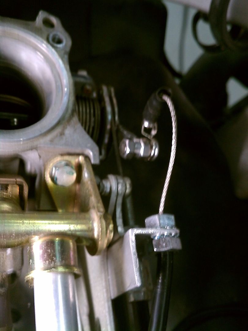
I'm having a problem with the cable binding on the bottom off the airbox after I release it from WOT.
Under the airbox I did clamp the breather hose out off the way like Mark did.
IMAG0670.jpg
 
Okay...so nobody has an issue with this.

After thinking about this all day at work I think I came up with a fix for my issue. Fabricating a new bracket to move the cable farther away and adding chain to the cable end. This will add more flexibility to the cable by letting the chain drop before the cable moves. At least it seems like it will work to me.
 
Re: ST1300 Rostra Cruise Control Installation

I finished the installation of the Rostra cruise control using the Gold Wing backlit control. A big thanks to altest1300 for his great instructions. He used the non-backlit control in his instructions. With the backlit control, some of the wire colors have changed from Al’s instructions.

Here are the updated wire colors and parts:

Gold Wing backlit control #35130-MCA-A21 from a 2005 Gold Wing. $137.85 from Hondaparts online.

Hook up 12V with a 4 amp fuse to the Black w/Yellow wire on the Gold Wing switch.

The Black w/Green wire hooks up to the Rostra Red/Brown wire.

The White w/Yellow wire hooks up to the Dark Green Rostra wire.

The White w/Blue wire hooks up to the Yellow Rostra Wire.

The Brown Rostra wire needs to be hooked up to a 10 amp switched circuit. I used a relay that is turned on by power from the Quartet Harness.

In the dipswitch settings, Al’s instructions state that switch 12 is in the “ON” position. The backlit switch is an open circuit switch, so number 12 needs to be in the OFF position.

The Rostra Blue Tach wire gets hooked up to the Blue w/Yellow coil wire. I just made a pig tale so I did not have to cut the coil wire.

To get the backlights to work, I ran switch power from the Quartet harness and hooked it up to the Light Green w/Black wire. This wire also had red squares on it. The solid dark green wire needs to be grounded. Now the backlights will work when the key is on.

If you want to use the Reverse Shift Switch to turn on and off Aux lights, you will use the Yellow w/White and Brown w/Green squares. I ran keyed power from the Quartet Harness to the Yellow/white and hooked the Brown wire to my Moto light relay.

If you have any LED’s for brake lights, you will need to put a relay in to get a good ground for the Rostra Violet wire. Wires to hook up to the relay: #85 to brake negative (+12v when brake is pressed), #86 to ground, #87 not used, 87A Rostra violet wire, #30 to ground.

Below is a photo of what the Gold Wing switch looks like with the lights on.

Can anyone tell me where the red wire from the Rostra connects to the GW switch(part of the yellow, green, B/R connectors for the control)? I don't see the wire listed here. (not the 4A red wire)
 
Any help would be appreciated. I would like to try and finish the wiring today. Looking at the wiring for the on/off CC switch it looks like it would be black/yellow but that is already used for the 4A fused red wire. Then I just have to figure out the brake light switch connection, purple-.
 
I think I got it figured out. I was looking for a wire to hook to the harness on the other end of the red 4A fuse which doesn't hook to them unless I splice it in. That is the + wire to brake light and violet is -.
 
I tied into the white/green and green/yellow from the front brake. I have everything connected but can't get the diagnostic light to come on. I have power and good ground coming into it so It's getting power.
 
I got the the led indicator to light. My + brake light wire needed to be hooked up to constant power. I hooked it up to the battery to test it and it worked. Now I need to figure out where + power from brake switch would be. There is none at the front brake.
 
Top Bottom