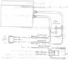
I installed my Symtec heated grips yesterday, but the wiring diagram they provided seems odd. Specifically, they show the low intensity wires attaching to the prong by the high intensity switch setting, and vica versa. This seems backwards to me, but maybe I just don't understand how the internals of the rocker switch work. The grips heated up in a brief test I did, but I haven't determined yet if the rocker switch on the "High" setting = high heat or low heat. Anyone else install these and can comment?

You are using an out of date browser. It may not display this or other websites correctly.
You should upgrade or use an alternative browser.
You should upgrade or use an alternative browser.
Symtec heated grip wiring question
- Thread starter nwguy
- Start date
Blrfl
Natural Rider Enhancement
What's in the diagram may be a little deceptive about how the switch works. There are a number of different switch designs, but the most common one switches the center pin ("common," where the 12 Volts DC from your battery goes in) to the opposite physical side of the switch.
If you have a continuity tester or ohm meter, you can check this for yourself. Disconnect everything from the switch, pop it into one position or the other and see which pin you see continuity on from the center.
--Mark
If you have a continuity tester or ohm meter, you can check this for yourself. Disconnect everything from the switch, pop it into one position or the other and see which pin you see continuity on from the center.
--Mark
Last edited:
Killtimer
The instructions were correct for my install. The prong under the "H", is indeed the low power setting and vise versa. I initially hooked them up the way I thought they should be....and then changed then. ")
OP
OP
Thank you both very much.
I just installed mine yesterday and thought the directions were just misprinted. I guess I'll head out to the garage and switch the wires around.
So, did any of you follow the instructions about attaching to a headlight, dashlight or taillight line? Or, did you back to a quartet or fuse block?
Any info might help me sort out the somewhat confusing instructions.
Any info might help me sort out the somewhat confusing instructions.
Killtimer
Mine are run from a switched line from the quartet harness.
ChipSTer
Growing old, but not up!
I just finished my Symtec install as well... I went with a heat-troller instead though... And tapped into my fuse block for power... I already love the heated grips and don't know how I managed to live without them...
I just got done installing the Symtec grip heaters as well as a Powerlet plug. Instead of going with the quartet harness I tapped into the accessory loom and just piggy-backed the accessory power and ground lines.
Pictures and a somewhat step-by-step are now on my blog.
Pictures and a somewhat step-by-step are now on my blog.
I have another question that the electrical guru's may have an answer for.
Symtec grip heaters have three leads, White,Red,Blue. Instructions are to wire white to white, blue to blue and red to red with the red being the grnd.
What would happen if another combination were used? Less heat? More Heat?
Symtec grip heaters have three leads, White,Red,Blue. Instructions are to wire white to white, blue to blue and red to red with the red being the grnd.
What would happen if another combination were used? Less heat? More Heat?
- Joined
- Feb 11, 2006
- Messages
- 8,056
- Location
- Jacksonville
- Bike
- GL1800 R1200RT NC700
- 2025 Miles
- 008307
I would guess:
1. They would not work.
2. Low on switch would be High heat, High on switch would be Low heat.
1. They would not work.
2. Low on switch would be High heat, High on switch would be Low heat.
No, I think I would get different levels of heat. I don't have a meter to check this out but ...what if I moved the white leads to ground, or the blue leads to ground instead of using the red leads for ground ?
Has anyone explored this ?
Has anyone explored this ?
SO .............I got an ohm meter and checked the various combinations.
Stock, ie RED as gnd....WHITE = high, BLUE= low heat settings.
BLUE as gnd - WHITE = really high and RED = low.
WHITE as gnd- BLUE= really high and RED = very high.
So the answer is they will work, it just depends on how hot you want your grips. Looks like the fctory wiring method is best all around.
Share: