I don't know if we have an article in the forum that explains how to get to the 5 way tee - it's difficult to search for one because the three words in that criteria (5 way tee) are all very short words, and they get rejected by the forum search engine.
Here's a quick & general explanation of the process. I can't guarantee that I have left a step out or forgotten something, because I'm writing this from memory rather than writing it as I carry out the task.
1) Run the fuel tank down to 1 or 2 bars. This is essential to empty the upper (main) fuel tank.
2) Remove the seat. Loosen (if necessary) the small rod that holds the aft end of the fuel tank in place - it runs horizontally across the motorcycle, just ahead of the seat height adjusting device (it is actually mounted on the seat height adjusting device bracket). By loosening it, you will be able to slide the upper fuel tank back an inch or so, allowing it to clear the handlebars when you lift the front of the tank up.
3) Remove the two bolts that hold the front end of the fuel tank in place. Now tilt the front end of the fuel tank up, and once it is a few inches above where it normally is, slide it backwards a bit. If your handlebars are stock, you will be able to hold the fuel tank up using the prop rod that is stored on the top of the molded plastic rear fender, underneath the passenger seat. If you have bar risers or other goodies attached to your handlebars, you might need to remove them.
There is a cable present that restricts how high up you can lift the front of the fuel tank. Unless you plan on replacing the L-shaped rubber hose that connects the upper and lower fuel tanks (a darn good idea, discussed a few paragraphs down), don't lift the front of the fuel tank higher than the cable allows.
4) Remove the top cover from the airbox - about 10 fasteners (all JIS). There is a little air temperature probe that is attached to the top cover of the airbox - easiest way to deal with it is to remove the two JIS screws that hold it in place, then pull aft on it to release it from the top cover of the airbox. Be darn careful not to drop either of these screws, if you do, you will never find the friggin' screw again and it will probably come to rest against a fuel hose or something critical like that and wind up killing you a year or two down the road. See this article:
Fuel Tank Hose - Near Miss.
5) Remove the air filter. What you should see now looks like the picture below (in this picture, the upper fuel tank has been completely removed from the bike)
Air Filter Enclosure with Snorkels in Place
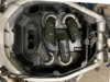 6)
6) Gently lift up the two tangs that cover the screws holding the snorkels in place on each of the four round brass-colour circular rings. In the picture above, these tangs have already been lifted up to show the JIS screws holding the snorkels down. Now take a picture of the snorkels so you will know how to re-install them. Note that there are little arrows moulded into the lower portion of the airbox showing how to line up the snorkels.
7) Once you have the snorkels off, you will find another 8 JIS fasteners (two per cylinder) holding the lower airbox to the throttle bodies. Remove these, try not to drop them into the throttle bodies when you are doing it (throttle body flaps will be closed if throttle grip is at idle, but still...)
8) Lift the lower airbox assembly up about an inch. There are a couple of hoses attached to the bottom of it, one at the front and one at the back, pay attention to how they attach as you disconnect them. Now remove the lower half of the airbox. Notice that rectangular rubber thing at the front of the airbox - that is the air inlet scoop, it picks up air from just above the radiator and feeds it to the engine. In theory, if you manipulate the lower half of the airbox 'just right', you can remove the lower half of the airbox with this part in place. In reality, unless you have done it dozens of times (like Larry), it's a heck of a lot easier to just disconnect that rubber part from the lower half of the airbox by pushing it around the edges (it is quite flexible), then you can lift it out (to clean it) after you have removed the lower portion of the airbox. Similarly, when re-assembling, put that rubber part back where it goes before putting the lower half of the airbox in place, and then work it into place with your fingers to make it snap into the lower half of the airbox once you have re-installed the lower half of the airbox, but before you start putting fasteners back in place.
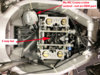
Once you have removed the lower half of the airbox, things will look like the picture below. The red arrow shows the 5 way tee.
Throttle Bodies and 5 Way Tee
Now that you are in there, here are a few tips that I learned at the foot of the master (Larry, AKA
@Igofar) when I observed him working on my bike:
a) Lift those three black tangs at the front of the rubber heat mat and take a peek in there at the thermostat & assorted cooling hoses - if you see leakage, maybe GENTLY snug up the hose clamps. Alternatively, consider replacing the hoses now that you have access to them - hoses don't last forever, and the oldest ST 1300s are now 17 years old.
b) Have an inspection mirror and bright flashlight handy to allow you to look under the throttle bodies and see if there is any evidence of rodent nests, etc. in there. If you do see problems, vacuum them out. At the same time, take a look at the drain hole at the very front of the 'V' of the engine and check to make sure it is not clogged with debris. This is the drain hole that lets water out of the 'V' of the engine, it leads to the "Square Hole" on the right side of the bike (more information here:
Water Pump Weep Holes).
c) There is an L-shaped hose (Honda PN 17545-MCS-R10) at the aft end of the upper fuel tank that connects the upper fuel tank to the lower fuel tank. This is a real safety-critical part. The cable that restricts how high you can lift the front end of the upper fuel tank (discussed above in point 3) is there to prevent you from overstressing (overbending) this rubber elbow. Unless you have done all the service on your moto yourself since buying it new, you don't know if someone else has overstressed it in the past... so, it is prudent to replace that L-shaped hose. It costs about $20. You will need a special tool -
Hose Clamp Pliers - to remove and replace the two self-tensioning spring clamps that hold the L-shaped hose in place.... they are very strong clamps. Here's a link to an article on the Australian ST site that explains how to replace the L-shaped hose:
Fuel Tank Joint Rubber pipe replacement procedure
If you plan to replace that L-shaped hose, then instead of propping up the upper fuel tank using the rod (discussed in step 3), REMOVE the whole darn upper fuel tank from the bike by unscrewing the rod that holds the aft end of the tank in place on the seat adjusting bracket, then disconnecting one end or another of the L-shaped hose using the hose clamp pliers. Then set the upper fuel tank aside. Personally, this is how I would go about it because it is a heck of a lot easier to do all the rest of the work when the upper fuel tank is removed from the bike, rather than just lifted up at a 45° angle. All the pictures above were taken with the upper fuel tank removed.
d) Use a pipe cleaner to clean out the 5 way tee. It is a rather fragile part, and it might break as you are taking hoses off it or putting hoses back on (it's cheap, don't worry), so don't do this job the night before you plan to leave for the best rally of the year.
e) If you have a manometer handy, now is the perfect time to synch the starter valves on the throttle bodies. See
here and
here for information about how to do that.
f) In the pictures above, my 5 way tee is resting on top of all the other hoses and wires under the throttle body. That's not how Honda assembled the bike - you will find your 5 way tee buried under all that other crap. So, to solve that problem permanently, proceed as follows:
i) Remove the vacuum hoses from the bike by using a pair of long needle-nose pliers to remove the throttle body end of each hose from the four throttle bodies, and the fifth hose from the vacuum sensor. Don't try and disconnect the 5 way tee end of the hose while it is in place in the bike - too much of a risk of busting the 5 way tee. Lift the whole spaghetti-like mess out and disconnect the old hoses from the 5 way tee at your workbench.
ii) Go to an auto supply store (Autozone, O'Reilly's, Pep Boys, etc.) and buy 2 feet of generic automotive vacuum hose. I don't know the correct size for the ST 1300, perhaps someone reading this might know and can post the specification. Anyway, just bring along a piece of the old vacuum hose to show the guy at the parts counter.
iii) Cut the new hose into lengths 2 inches longer than the old hoses and install the newly cut hoses onto the throttle bodies and the vacuum sensor. They will be too long by about an inch or so - don't worry about this, the extra length makes it easier to do the next step.
iv) Route the new hoses on top of all the other crap, as shown in the 2nd picture above. Put them all together in the middle, then hold the 5 way tee over top, and snip the new hoses to the correct length. Now install the (freshly cleaned out) 5 way tee on the new hoses.
g) It makes sense to replace the air filter now if it is anywhere near due for replacement.
9) Some tips for re-assembly, all learned from the School of Hard Knocks:
a) Don't forget to put that rubber air scoop in place under the lower part of the airbox before you re-install the lower part of the airbox.
b) Don't forget to connect the hoses to the underside of the lower part of the airbox before you start putting fasteners in to hold the lower part of the airbox in place.
c) After you re-install the snorkels, just bend those little tabs down enough to retain the JIS bolt in place if it were to work loose. You don't have to hammer them in place over the bolt head. They are there to prevent a bolt that loosens up from coming out of its hole and getting sucked down a snorkel into the engine.
d) Don't forget to put the air filter in before you put the top cover of the airbox on.
e) Don't forget to re-connect the air temperature sensor to the top of the airbox.
f) If you removed the upper fuel tank, don't forget to re-connect the little cable at the front that restricts upward movement, and to re-install the bar at the back of the tank that attaches it to the seat adjustment mechanism frame.
g) If you have removed the fuel tank, it's easier to re-install it, and especially easier to install the L-shaped hose and the two clamps that hold the L-shaped hose in place if you re-install the fuel tank before you install the lower half of the airbox. You will have much more room in there to work and get your hose clamp pliers onto the two clamps of the L-shaped hose.
Hope this helps you - it's not a thorough and scholarly article that lists every single step in the process, it's just an overview of what is involved. I do highly recommend that you get a Honda Service Manual for the ST 1300 before attempting this level of disassembly - the service manual does contain step by step instructions.
Michael


")


