
Camshaft moved after timing belt off (newbee)
- Thread starter Peto
- Start date
Back when I was riding GL1000's, I got into the habit, taught to me by an even older bikefixr, to rotate the engine to the timing marks per the manual and highlight mark them with a marker. I found that black, silver, white or red are usually easy to see depending on the metal color...more so than the plain stamped marks. Just paint them, on the crank, pulleys and case. Makes it more difficult to miss. Do follow the manual procedure for whatever you are working on.
sure I will, thxBack when I was riding GL1000's, I got into the habit, taught to me by an even older bikefixr, to rotate the engine to the timing marks per the manual and highlight mark them with a marker. I found that black, silver, white or red are usually easy to see depending on the metal color...more so than the plain stamped marks. Just paint them, on the crank, pulleys and case. Makes it more difficult to miss. Do follow the manual procedure for whatever you are working on.
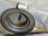
I am trying that one, right now. First I couldn't find the punch marks on the camshaft bearings. I took a picture of it and it is clear.I'd rather look for the marks given in the workshop manual graphic shown in post #4
Erdoc48
Site Supporter
- Joined
- Jan 25, 2009
- Messages
- 1,441
- Age
- 59
- Location
- Myrtle Beach, SC/ Sometimes Colorado
- Bike
- 94/00/04 STs, FSC600
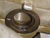
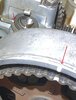
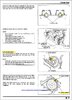
Hate to ask, but is that little punch mark on the cam just a factory defect (I don’t recall seeing that on mine when I changed my belt)? The line/ indented region I thought is what’s important in lining up everything. That illustration from the service manual is a bit confusing.
Last edited:
ST1100Y
Site Supporter
LOL! That's a new one, seems someone left his marks in there...I am trying that one, right now. First I couldn't find the punch marks on the camshaft bearings. I took a picture of it and it is clear.
") (wondering about the past of this motorcycle...)
(wondering about the past of this motorcycle...)LHS cams have the punch marks, RHS cams have the index lines... always... ID the OEM ones and work from there
And if they won't align at the head-surface as shown, you'll have to remove the cam to get it properly set on the reduction gear...
Ideally will the belt pulleys now also align nicely with their markings; if not you'll have to rearrange the cams on the reduction gear till they do.
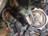
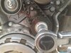
Crank on T1 & punch mark as shown, T-belt on, let spanner snap on it and tighten.
Assuming that plugs are already out take a ratchet with a 17mm nut and slowly rotate engine at the crank pulley by hand till all T-belt markings align again... should go smoothly...
(Had such a case in the past: cams were off at the drive, and to "compensate" someone flipped the timing belt a few teeth... needless to say the poor engine ran like crap...)
This is what I understood from the manual and explained by mr DwalbyHate to ask, but is that little punch mark on the cam just a factory defect (I don’t recall seeing that on mine when I changed my belt)? The line/ indented region I thought is what’s important in lining up everything. That illustration from the service manual is a bit confusing.
page 8-13
both cams have both marks.LOL! That's a new one, seems someone left his marks in there...
LHS cams have the punch marks, RHS cams have the index lines... always... ID the OEM ones and work from there
the index lines will align with the top edge of the head when that side of the engine is at TDC, so that's why at TDC #1 you're going to expect the index lines to match up on the right cam, as shown in the service manual picture shown earlier.
At that same crank position, the punch marks align with the top edge of the head on the left side because that side isn't at TDC, its 90° before TDC. But, the left cams also have index lines, which will align when that side reaches TDC after 90° more crank rotation.
The cams rotate counter-clockwise, because they are driven by a gear on the cam sprocket. The sprocket rotates clockwise, same as the crank, the gear driven cam rotates counter-clockwise.
In the picture recently posted by the OP, if you look at the relation of the punch marks to the index lines you'll see that after the cams rotate another 45° (90° of crank rotation) the index line will then align with the top of the head (and in fact that's the position they are in since the cam sprocket has rotated after the timing belt was removed).
the picture the OP posted is NOT the RHS, its the LHS, after his cam sprocket has moved unintentionally.
Guys I have some updatesHi everyone,
I have question about left camshaft timing on the Hobda ST1100 pan European 1992. I wanted to replace the timing belt.
So I have lined up the crankshaft punch mark with the notch on case perfectly.
The left and right camshaft were also aligned.
But than something went wrong, during the process of refitting the timing belt
I have moved the left camshaft beyond the mark on the reduction holder case and it pops 1/4 further. It felt like a spring moved the valve. I could hear it. So I stop to prevent damage to the engine.
And it can not turn anti clockwise.
All the other markings are still aligned.
Question:
Can I moved the camshaft 1 turn to align it back, without turn crankshaft and the right camshaft.
How can I align this back. The I need to rebuild the entire engine?
Thx in advance.
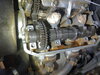
First I removed the cams and rotate the pulley to align the index mark with the reduction holder.
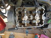
Than I installed the timing belt, see the markings.
The upper camshaft was easy to align with the punch marks outward.
Now I have to install the lower camshaft, but that is quite difficult to get back. The cam is pushing against the valve which make it difficult to align the punch mark and install
Any suggestions how to get this last one done?
Attachments
-
 152.9 KB Views: 7
Last edited:
line it up with your best guess, and torque down the bearing caps, it will compress the valves and then you'll see if you guessed right or not. If you're off by a gear tooth either way, adjust and repeat.
what some people have done in the past, and it just didn't get mentioned in this thread earlier, is to wipe the oil off a few teeth on each cam and mark the original positioning between the gears with a sharpie marker. (or maybe they did that with the timing belt and cam sprockets, now I don't remember for sure) I've never marked anything myself, and I think the couple of times I've removed the cams over the years for a valve adjust my first guess turned out to be correct when I reinstalled.
I can't recall if the cam turns a little while torquing down the bearing caps or not, maybe someone else with more recent experience with this procedure can chime in.
If it looks like the cam will just move straight down and mesh with the cam drive gear below, try it with the punch mark level with the head as your first guess.
The split gears need to be pushed into a tensioned position and that does cause a small cam rotation as the saddles are torqued down. But as suggested if that does not line up properly, just remove the saddles and reposition the cam as needed.
It was hard to reinstall than I realize I could jump to page 8-7 of the manual, which I did.Guys I have some updates
First I removed the cams and rotate the pulley to align the index mark with the reduction holder.
Than I installed the timing belt, see the markings.
The upper camshaft was easy to align with the punch marks outward.
Now I have to install the lower camshaft, but that is quite difficult to get back. The cam is pushing against the valve which make it difficult to align the punch mark and install
Any suggestions how to get this last one done?
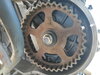
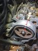
I turned the crankshaft clockwise to TF4, with only the upper camshaft installed, which was aligned with the punch mark outward.
The punch mark on the drive pulley for the camshaft align with the notch and then I saw that the upper chamshaft bearing was aligned with the index mark outward.
Which I was happy to see. So I reinstall the lower camshaft with the index facing outward.
Guys thx a lot for the help especially mr dwalby.
Last edited:
Yes, I followed the manual. The challenge was what to do if the drive pulley for the cams moved past the marking. That part was not mentioned.I'd rather look for the marks given in the workshop manual graphic shown in post #4
glad to see you got everything back together.
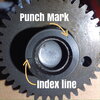
Interesting, I never realized that there is a punch mark on the cam drive sprocket (the one that the timing belt rides on) in addition to its index line. Good to know.
Also, to summarize the LHS cam positions at the various positions of interest, we have:
#1 TDC - punch marks facing outward
#4 TDC (90° further crank rotation) - index lines facing inward
#3 TDC (270° crank rotation) - punch marks facing inward
#2 TDC (90° crank rotation) - index lines facing outward
Last edited:
John OoSTerhuis
Life Is Good!
Not my image. Sorry, I didn’t make a note for attribution.
The split gears need to be pushed into a tensioned position and that does cause a small cam rotation as the saddles are torqued down. But as suggested if that does not line up properly, just remove the saddles and reposition the cam as needed.
Yes that's it. The punch mark could be easy overlooked.Not my image. Sorry, I didn’t make a note for attribution.
Last edited:
I have checked only #1 (=TF1 crankshaft aligned) and #2 (TF4 crankshaft aligned) for the left cylinder.glad to see you got everything back together.
Interesting, I never realized that there is a punch mark on the cam drive sprocket (the one that the timing belt rides on) in addition to its index line. Good to know.
Also, to summarize the LHS cam positions at the various positions of interest, we have:
#1 TDC - punch marks facing outward
#4 TDC (90° further crank rotation) - index lines facing inward
#3 TDC (270° crank rotation) - punch marks facing inward
#2 TDC (90° crank rotation) - index lines facing outward
Well that is good advice to prevent damage thread. And I ordered new valve cover gasket sets.Everyone is focusing on getting the timing belt lined up. You will get there, but when you start reassembling the engine....
1. The 1300 valve cover gasket can usually be reused. However, there are two half moon (semi circular) depressions that need a sealant between metal and gasket - RTV is often used. I'm writing about the 1300 - check to see if what I am saying goes for the 1100.
2. When you replace the valve cover, it is easy to catch the rubber heat shield between the cylinder head and the cover. This will lead to an oil leak. Just be careful and go slowly.
3. Make sure the valve cover bolts go into their threaded holes correctly and do not overtighten them. Finger tighten them before using a wrench. They are small bolts and will strip out the aluminum threads. You are also putting them into a cylinder head that is canted, which makes aligning them more difficult. Now is the time to change the little rubber washers under these cover bolts. These compress over time and can weep oil.